

Method for manufacturing honeycomb structure
- Summary
- Abstract
- Description
- Claims
- Application Information
AI Technical Summary
Benefits of technology
Problems solved by technology
Method used
Image

Examples
example 1
[0091]As ceramic raw materials, a SiC powder and a metal
[0092]Si powder were mixed at a mass ratio of 80:20, and with the mixture were mixed methyl cellulose and hydroxypropoxymethyl cellulose as forming auxiliaries and starch and water-absorbing resin as pore former. Then, a surfactant and water were added to the mixture, and they were kneaded to obtain a circular columnar kneaded clay by a vacuum kneader.
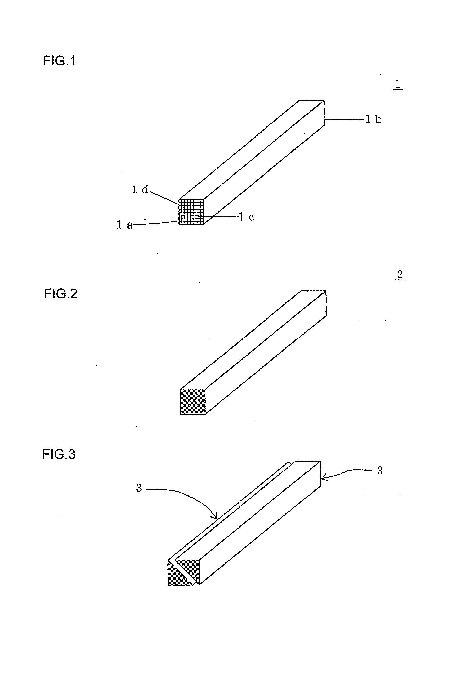
[0093]The circular columnar kneaded clay was formed into a honeycomb shape by the use of an extruder, and, after the resultant was subjected to high frequency dielectric heating drying, it was dried at 120° C. for five hours by the use of a hot air drier. Then, a predetermined amount of both the end portions were cut off to obtain a quadrangular prism honeycomb formed body having a partition wall thickness of 310 μm, a cell density of 46.5 cells / cm2, a square bottom face having a size of 36 mm×36 mm, and a length of 300 mm. Fourteen honeycomb formed bodies were produced.
[0094]In t...
examples 2 and 3
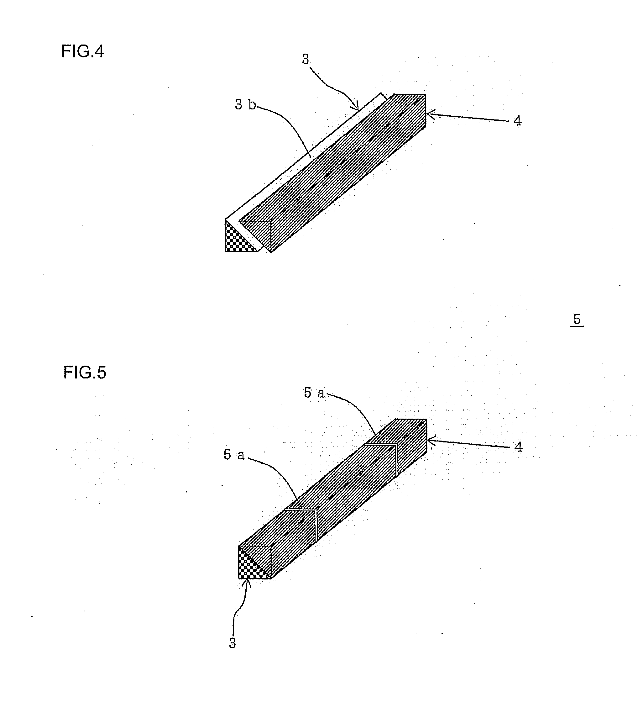
[0103]Each of the honeycomb structure was manufactured in the same manner as in Example 1 except that the structure of the block body and the number of the formed bodies were changed as shown in Table 1.
example 4
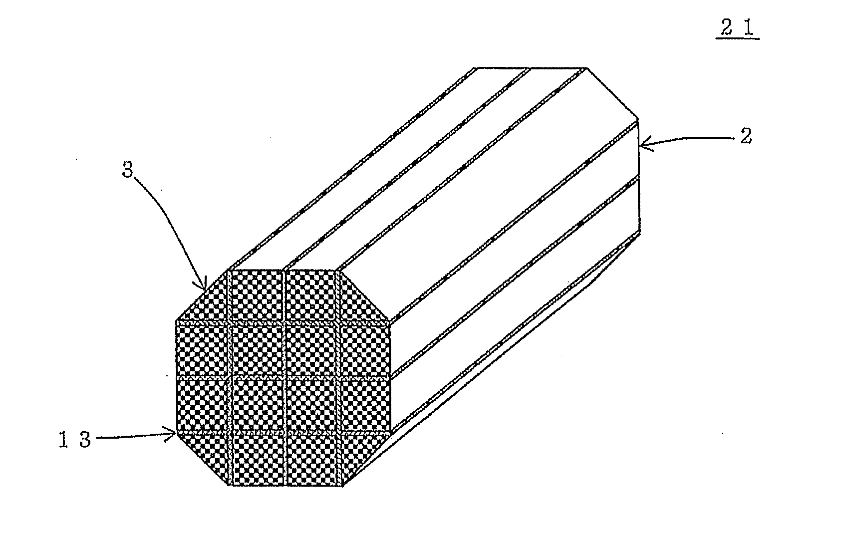
[0104]A honeycomb structure was manufactured in the same manner as in Example 1 except that the honeycomb block body 42 having a “3×6 structure” with a “grinding pattern C” as shown in FIG. 13 was produced and that the honeycomb structure was made to have a columnar shape having an elliptic bottom face. The grinding pattern C has an elliptic shape inscribed in the honeycomb block body in a cross section perpendicular to the central axis of the honeycomb block body with the major axis of the elliptic shape having the same length as the length in the longer axial direction (length in the direction where six quadrangular prism honeycomb fired bodies stand in a line of the honeycomb block body) and the minor axis of the elliptic shape having the same length as the length in the shorter axial direction (length in the direction where three quadrangular prism honeycomb fired bodies stand in a line of the honeycomb block body). The structure and grinding pattern of each honeycomb block body...
PUM
| Property | Measurement | Unit |
|---|---|---|
| Pressure | aaaaa | aaaaa |
| Shape | aaaaa | aaaaa |
Abstract
Description
Claims
Application Information