Solid state energy storage device and method

a technology of energy storage device and solid state, which is applied in the direction of reduction-oxidation hybrid capacitor, electrolytic capacitor, coating, etc., can solve the problems of limiting the pseudo-capacitance of materials, limiting the use of ruthenium oxide, and many suitable metal oxides are expensive and thus impractical for large-scale us

Active Publication Date: 2011-10-06
GOVERNMENT OF THE UNITED STATES AS REPRESENTED BY THE SEC OF THE NAVY
View PDF2 Cites 43 Cited by
  • Summary
  • Abstract
  • Description
  • Claims
  • Application Information

AI Technical Summary

Benefits of technology

[0014]A method of forming an energy storage device comprising the steps of mixing an aprotic polar polymer with a salt in a liquid solution to form a dissolved mixture, adding at least one mediator to the dissolved mixture, adding active carbon to the dissolved mixture, sonicating the dissolved mixture for at least one hour, and loading the mixture onto a first side and a second side of a separator membrane and substantially removing the liquid solution.

Problems solved by technology

However, this may be the limit for ruthenium oxide, with a maximum specific energy capacity of about 30 watt hour / kilogram.
Often the metal oxide layer of a pseudo-capacitor is crystallized such that RuO2 in the middle of the layer is inaccessible for electron transfer with the electrode, thus limiting the pseudo-capacitance of the material.
Further, many suitable metal oxides are expensive and thus impractical for large scale use.
Aqueous electrolytes can leak and corrode.
They also limit the voltage and operating temperature of the capacitor.
Solid state electrolytes are known, but they generally have low conductivity resulting in high internal resistance.
Furthermore, the high cost of ruthenium and other suitable metals for the oxide layer hinders the wide application of these devices.
Furthermore, many pseudo-capacitors degrade with use and are not suitable for applications requiring durable, long lasting electronics.

Method used


Image

  • Solid state energy storage device and method
  • Solid state energy storage device and method
  • Solid state energy storage device and method

Examples


Embodiment Construction

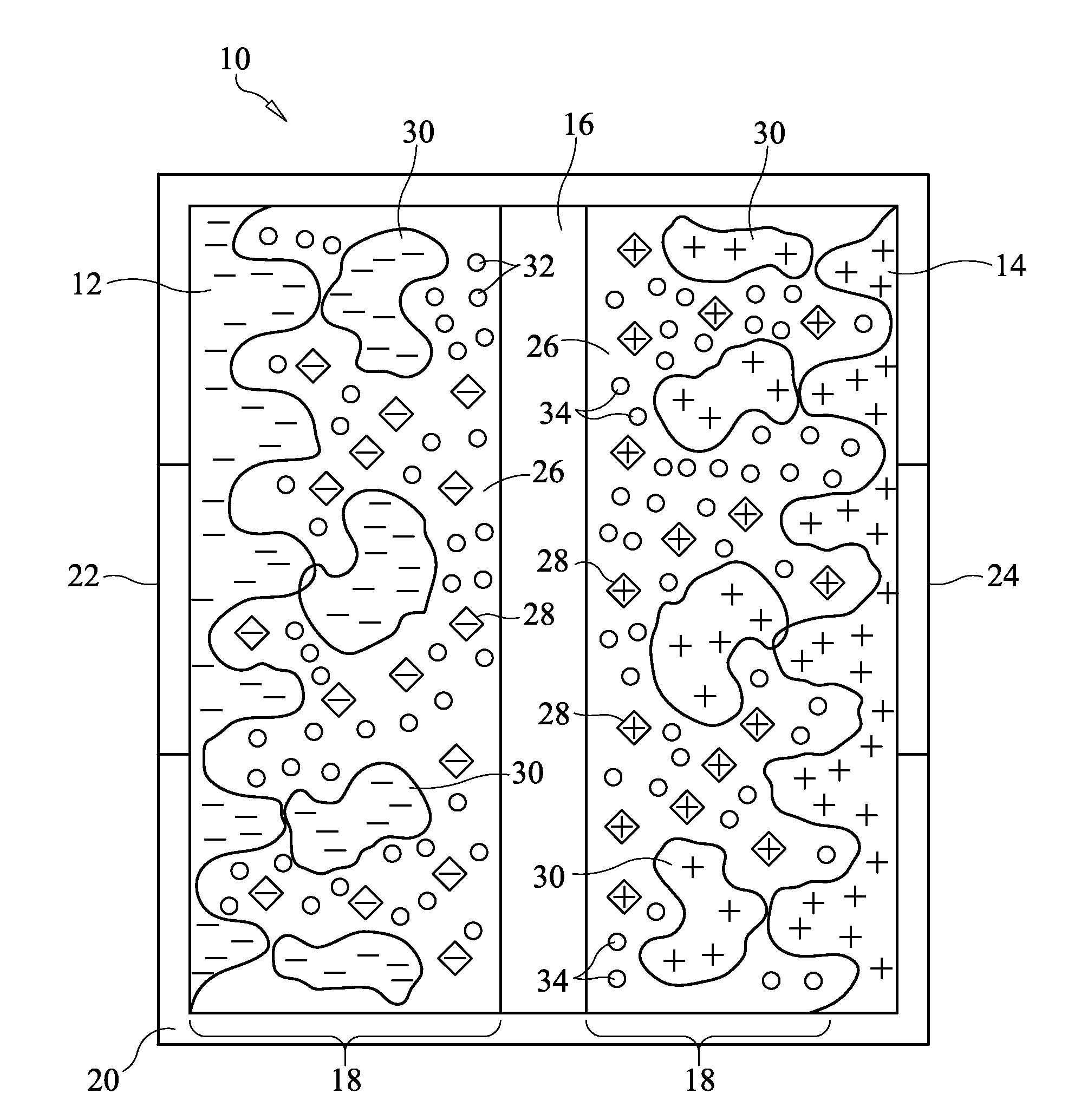
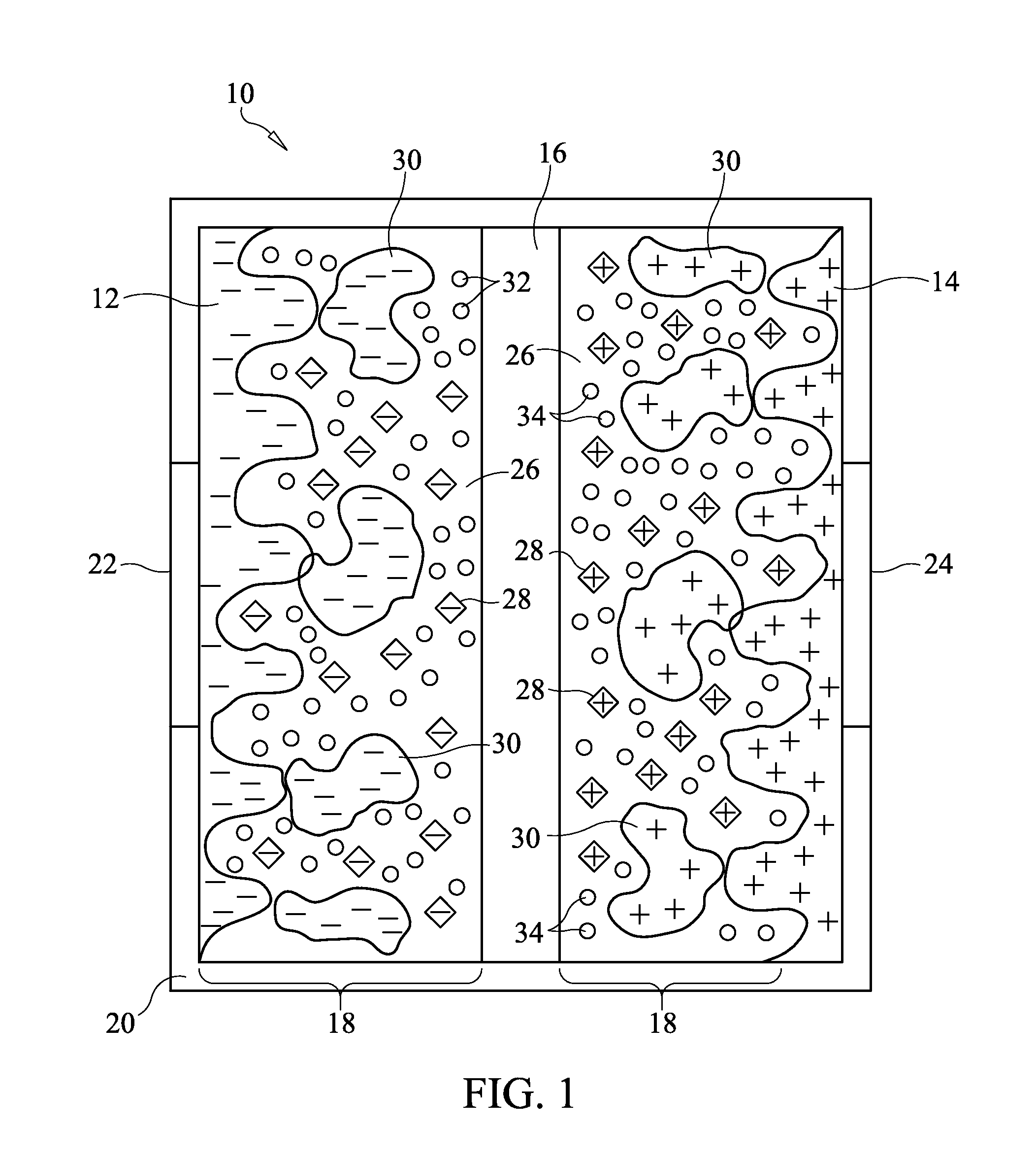
[0026]The present invention provides an energy storage device and methods of manufacture and use thereof. A single-cell double layer capacitor may have two electrodes which store charge separated by a permeable membrane separator. The membrane separator permits ion flow but is an electronic non-conductor. Each electrode is in contact with a current collector which provides electric current conduction out of the capacitor package for use. The electrodes and the membrane are filled with an electrolyte, and the entire assembly is contained in inert, non-conductive packaging. Multiple cells may be connected in series or in parallel in the final solid state package.

[0027]Referring now to the drawing figures in which like reference designations refer to like elements, an embodiment of a solid state energy storage device 10 constructed in accordance with principles of the present invention is shown in FIG. 1. As used herein, “energy storage device,”“capacitor” and “supercapacitor” all refe...


PUM


Abstract

A solid state energy storage device has two electrodes, a membrane separator and a solid electrolyte having a substantially solid solvent, a salt and a mediator. The energy storage device stores electric charge by both Faradaic and non-Faradaic systems. The energy storage device may include activated carbon mixed with the electrolyte and sonicated to provide connection between the activated carbon and the mediator. The energy storage device is hot pressed to increase conductivity. The two electrodes may be asymmetric in amount of reduced and oxidized species of mediator.

Description

STATEMENT REGARDING FEDERALLY SPONSORED RESEARCH OR DEVELOPMENT[0001]The U.S. Government has a paid-up license in this invention and the right in limited circumstances to require the patent owner to license others on reasonable terms as provided for by the terms of Grant Number N000140810332 awarded by the Office of Navy Research.CROSS-REFERENCE TO RELATED APPLICATION[0002]n / aFIELD OF THE INVENTION[0003]The invention relates to systems and methods of making solid state energy storage devices. More particularly, the invention relates to systems and methods of solid state electrochemical energy storage devices utilizing redox materials and electrochemical double layers to increase capacitance.BACKGROUND OF THE INVENTION[0004]Capacitors are used in electronic systems for a variety of functions, for example to block direct current while allowing alternating current to pass, smoothing the output of a power supply, reducing interference, and as sources for short, high power pulses of elec...

Claims


Application Information

Patent Timeline
Patent Type & Authority Applications(United States)
IPC IPC(8): H01G9/02H01G9/038H01G9/058B05D5/12
CPCH01G9/02H01G9/038H01G9/058H01G9/022H01G11/02H01G11/56Y02E60/13H01G9/155H01G11/04H01G11/52
Inventor ZHOU, XIANGYANGZHOU, JUANJUANMANSOUR, AZZAM N.
Owner GOVERNMENT OF THE UNITED STATES AS REPRESENTED BY THE SEC OF THE NAVY
Why Eureka
Try Eureka