Projection image generation apparatus and method, and computer readable recording medium on which is recorded program for the same

a technology of projection image and projection image, which is applied in the direction of diagnostic recording/measuring, tomography, instruments, etc., can solve the problems of difficult to understand the position where the treatment tool enters an organ, and difficult to understand whether or not such a structure is present in the path of the treatment tool, so as to improve the accuracy and safety of surgery.

Active Publication Date: 2011-10-06
FUJIFILM CORP
View PDF10 Cites 35 Cited by
  • Summary
  • Abstract
  • Description
  • Claims
  • Application Information

AI Technical Summary

Benefits of technology

[0033]According to the present invention, when generating, using a three-dimensional medical image which includes a second structure masked by a first structure when the first structure is viewed from an assumed position of a treatment tool as input, a projection image which is an image formed of image information on a plurality of visual lines from a given viewpoint being projected on a given projection plane, an intersection point between an assumed path formed when the treatment tool is moved from the assumed position towards the second structure and the surface of the first structure is detected, and the intersection point is displayed in an identifiable manner at a position on the projection plane of the projection image to which image information on a visual line connecting the viewpoint and the intersection point is projected. This allows the entry position of the treatment tool into the first structure masking the second structure, i.e., an attention target, to be understood in the projection image from the given viewpoint. If the projection image from the given viewpoint is used as an image from a viewpoint used in ordinary diagnosis, surgery simulation, or surgery navigation, the observer may understand the state of the approaching path of the treatment tool to an attention structure (second structure) masked by another structure (first structure), like a lesion in an organ, with the same feeling as that when observing an affected area in ordinary surgery without having uncomfortable feeling or confusion, which contributes to the improvement of the accuracy and safety of surgery.

Problems solved by technology

This makes it difficult, even by observing, in perspective, a lesion in an organ using virtual endoscopic images from endoscope viewpoints described in the patent documents described above, to understand the operation direction of the treatment tool, i.e., the state in an approaching path of the treatment tool towards a lesion in the images.
For example, for a virtual endoscopic image in which the visual direction VL corresponds to the center of the field of view, as schematically illustrated in FIG. 7, it is difficult to understand a position where the treatment tool enters into an organ.
Although it is possible to observe other structures present in the organ, such as a blood vessel and the like, to be taken into account for the surgery by translucent processing, it is difficult to understand whether or not such a structure is present in the path of the treatment tool from the entry position to the lesion.

Method used


Image

  • Projection image generation apparatus and method, and computer readable recording medium on which is recorded program for the same
  • Projection image generation apparatus and method, and computer readable recording medium on which is recorded program for the same
  • Projection image generation apparatus and method, and computer readable recording medium on which is recorded program for the same

Examples


first embodiment

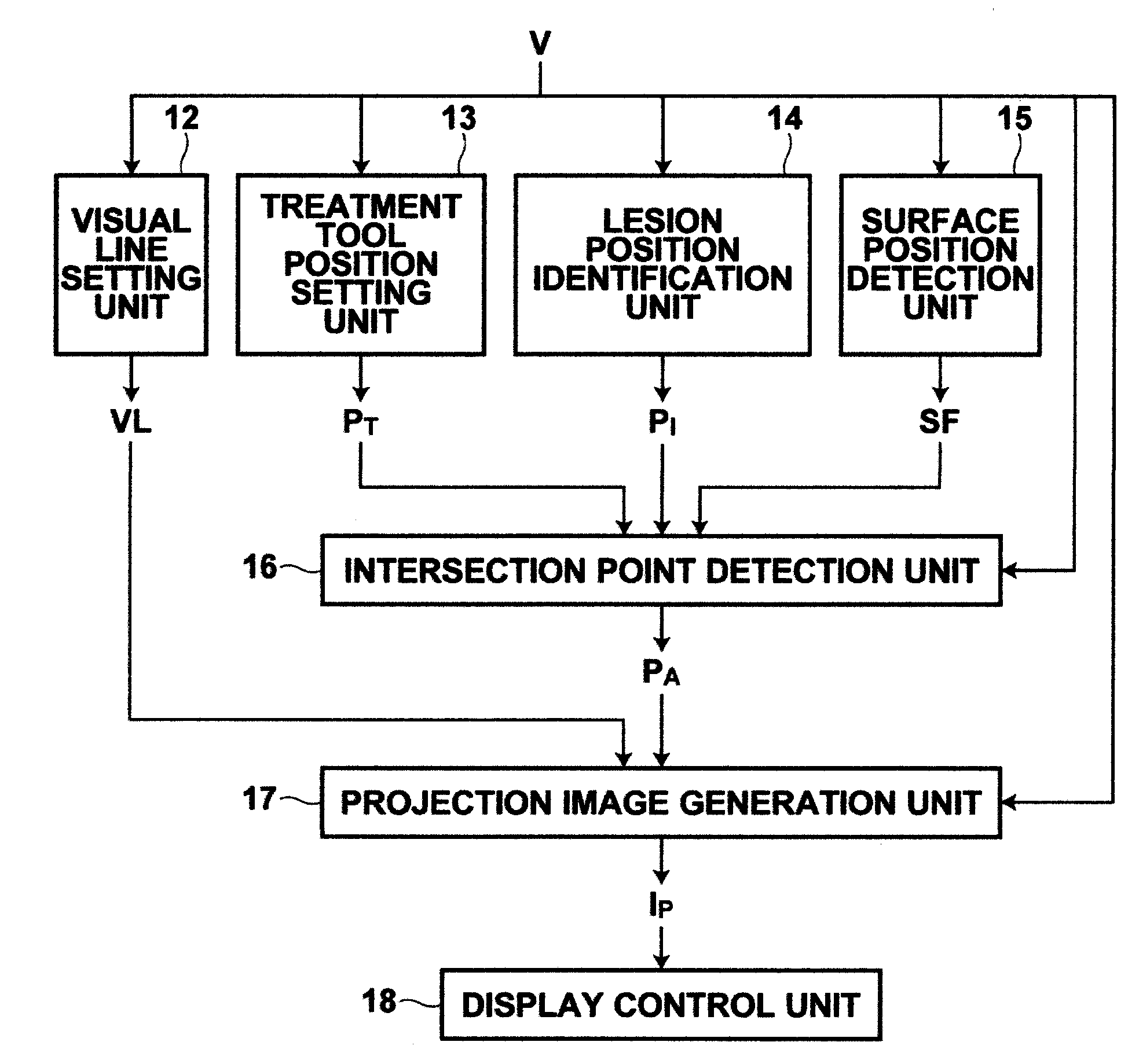
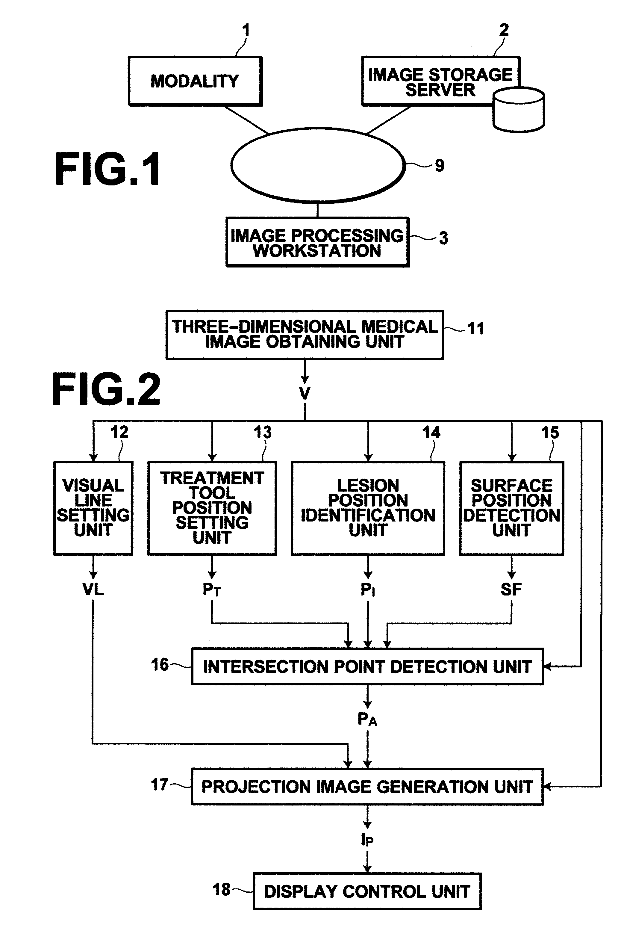
[0050]FIG. 1 is a schematic hardware configuration diagram of a medical image diagnosis system in which a surgery simulation function is implemented according to the present invention. As shown in FIG. 1, the system includes modality 1, image storage server 2, and image processing workstation 3 communicatably connected to each other via network 9.

[0051]Modality 1 includes an apparatus that images an inspection target region of a subject to generate image data representing a three-dimensional medical image of the region and outputs the image data by attaching auxiliary information defined in DICOM (Digital Imaging and Communication in Medicine) standard as image information. Specific examples of the apparatus include, for example, CT, MRI, and the like. In the present embodiment, a description will be made of a case in which three-dimensional image data representing an abdominal region of a human body, including liver, to be examined are generated by scanning the human body with CT i...

second embodiment

[0076]the present invention is an embodiment in which color information CX (≠0) and opacity αX (0XX inside of a liver, such as a blood vessel, and the opacity αI of the lesion area PI is changed in the range of 0I16 and projection image generation unit 17 do not perform the processing integrally, and the processing is performed in the order of intersection point detection unit 16 and projection image generation unit 17 or in the reverse order, as described above.

[0077]This causes a structure PX which has the color information CX and opacity αX allocated thereto and lies on the straight line connecting between the treatment tool position PT and lesion area PI, as well as the lesion area PI, is projected on the surface SF of the liver when the ray casting is performed by intersection point detection unit 16 in the operation direction TL of the treatment tool, as schematically illustrated in FIG. 9. FIG. 10 schematically illustrates a projection image IP generated in the second embodim...

fifth embodiment

[0080]the present invention is an endoscopic examination support system in which a surgery navigation function is implemented. FIG. 13 is a hardware configuration diagram of the endoscopic examination support system, illustrating an overview thereof. As shown in FIG. 13, the system includes endoscope 101, digital processor 102, light source unit 103, real endoscopic image display 104, modality 105, treatment tool 106, endoscope marker 107a, treatment tool marker 107b, position sensor 108, image processing workstation 109, and display 110 for the image processing workstation (hereinafter, WS display).

[0081]In the present embodiment, endoscope 101 is a rigid endoscope for abdominal cavities and inserted into an abdominal cavity of a subject. The light guided through an optical fiber from light source unit 103 is outputted from a tip portion of endoscope 101 and an image of the inside of the abdominal cavity of the subject is obtained by an imaging optical system of endoscope 101. Digi...


PUM


Abstract

When generating a projection image which is an image formed of image information on a plurality of visual lines viewing a first structure in a three-dimensional medical image from a given viewpoint being projected on a given projection plane, setting an assumed position of a treatment tool in the three-dimensional image, detecting a surface of the first structure from the three-dimensional medical image, identifying a second structure in the three-dimensional medical image located at a position masked by the first structure, detecting an intersection point between an assumed path formed when the treatment tool is moved from the assumed position towards the second structure and the surface of the first structure, and displaying the intersection point in an identifiable manner at a position to which image information on a visual line connecting the viewpoint and the intersection point is projected.

Description

BACKGROUND OF THE INVENTION[0001]1. Field of the Invention[0002]The present invention relates to a technology for generating a projection image which is an image formed of image information on a plurality of visual lines viewing a structure in a three-dimensional medical image from a predetermined viewpoint being projected on a predetermined projection plane.[0003]2. Description of the Related Art[0004]Recently, with the advancement of modalities, such as multidetector-row CT (MDCT), high quality three-dimensional image data have become available. In image diagnosis using such image data, virtual or pseudo three-dimensional subject images have been used more frequently, as well as high resolution cross-sectional images. Further, the extraction of organ structures from three-dimensional medical images using image recognition technologies are also performed, and it has become possible to generate virtual or pseudo three-dimensional images from three-dimensional medical images of well ...

Claims


Application Information

Patent Timeline
Patent Type & Authority Applications(United States)
IPC IPC(8): A61B6/03G06K9/00
CPCA61B6/032G06T2210/41G06T15/08
Inventor MIYAMOTO, MASAKI
Owner FUJIFILM CORP
Why Eureka
Try Eureka