Apparatus for separation of gas-liquid mixtures and promoting coalescence of liquids

a technology of apparatus and gas mixture, which is applied in the direction of liquid separation, dispersed particle separation, reversed direction vortex, etc., can solve the problem of reducing the requisite residence time in the separation device, and achieve the effect of promoting droplet coalescence, reducing the momentum of the incoming flowing mixture, and promoting gas separation

Active Publication Date: 2011-10-13
SAUDI ARABIAN OIL CO
View PDF15 Cites 167 Cited by
  • Summary
  • Abstract
  • Description
  • Claims
  • Application Information

AI Technical Summary

Benefits of technology

[0019]a. global flow deceleration to decrease the momentum of the incoming flowing mixture;
[0020]b. application of a controlled centrifugal effect to promote droplet coalescence in the liquid phases; and
[0021]c. application of a cyclonic effect to promote separation of gas from the liquid phases.
[0022]Installation of the inlet conditioning apparatus

Problems solved by technology

The apparatus is not intended as a replacement for water and oil separation devices; rather, it promotes droplet coalescence and gas separation f

Method used


Image

  • Apparatus for separation of gas-liquid mixtures and promoting coalescence of liquids
  • Apparatus for separation of gas-liquid mixtures and promoting coalescence of liquids
  • Apparatus for separation of gas-liquid mixtures and promoting coalescence of liquids

Examples


example

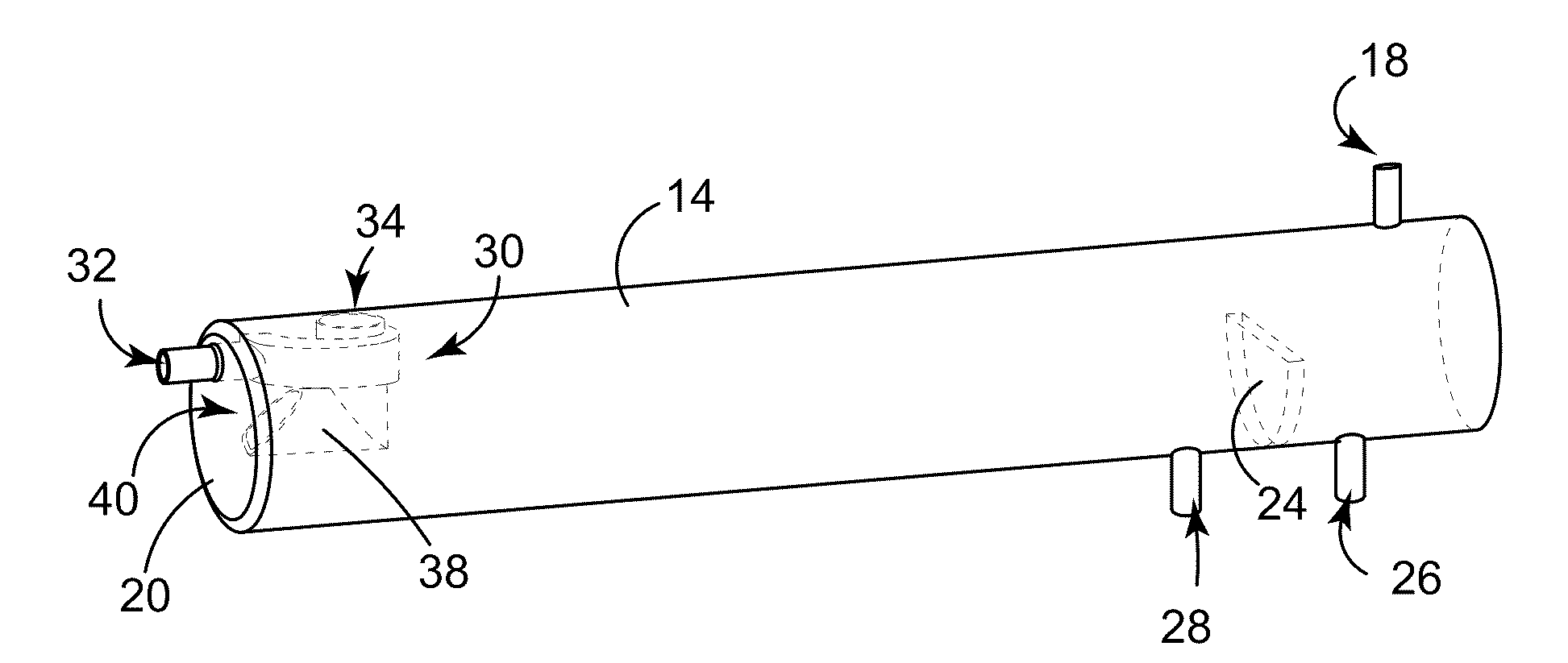
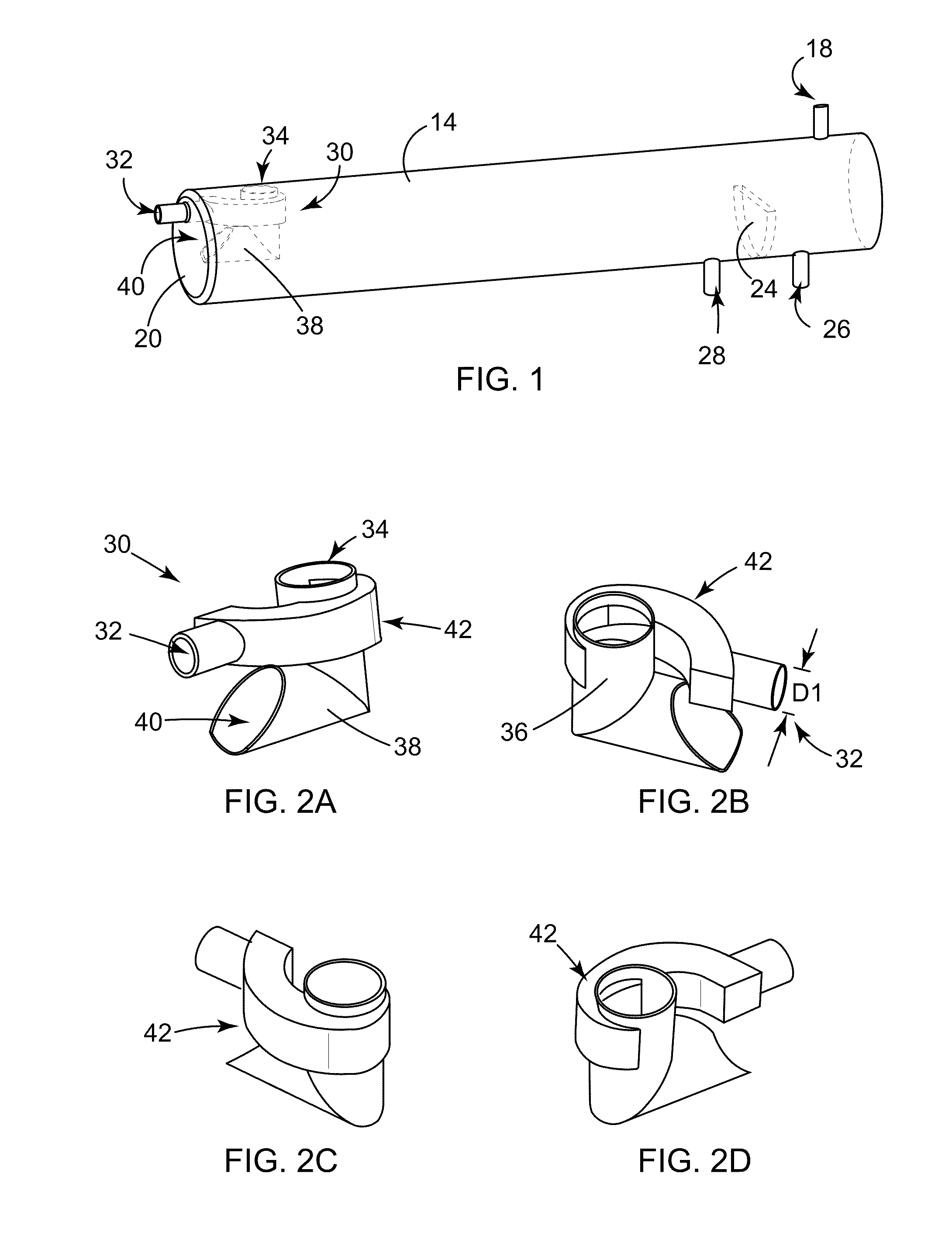
[0079]High density computer simulations were conducted to approximate the flow of a multiphase fluid into a horizontally-oriented gas oil separation vessel. A first model vessel includes a conventional momentum breaker box 31 at the inlet (FIG. 12A). A second model vessel includes a conditioning apparatus 30 (FIG. 13A) as described herein. The model of each vessel includes a gas outlet 18, water outlet 28, overflow wall or baffle 24, and oil outlet 26.

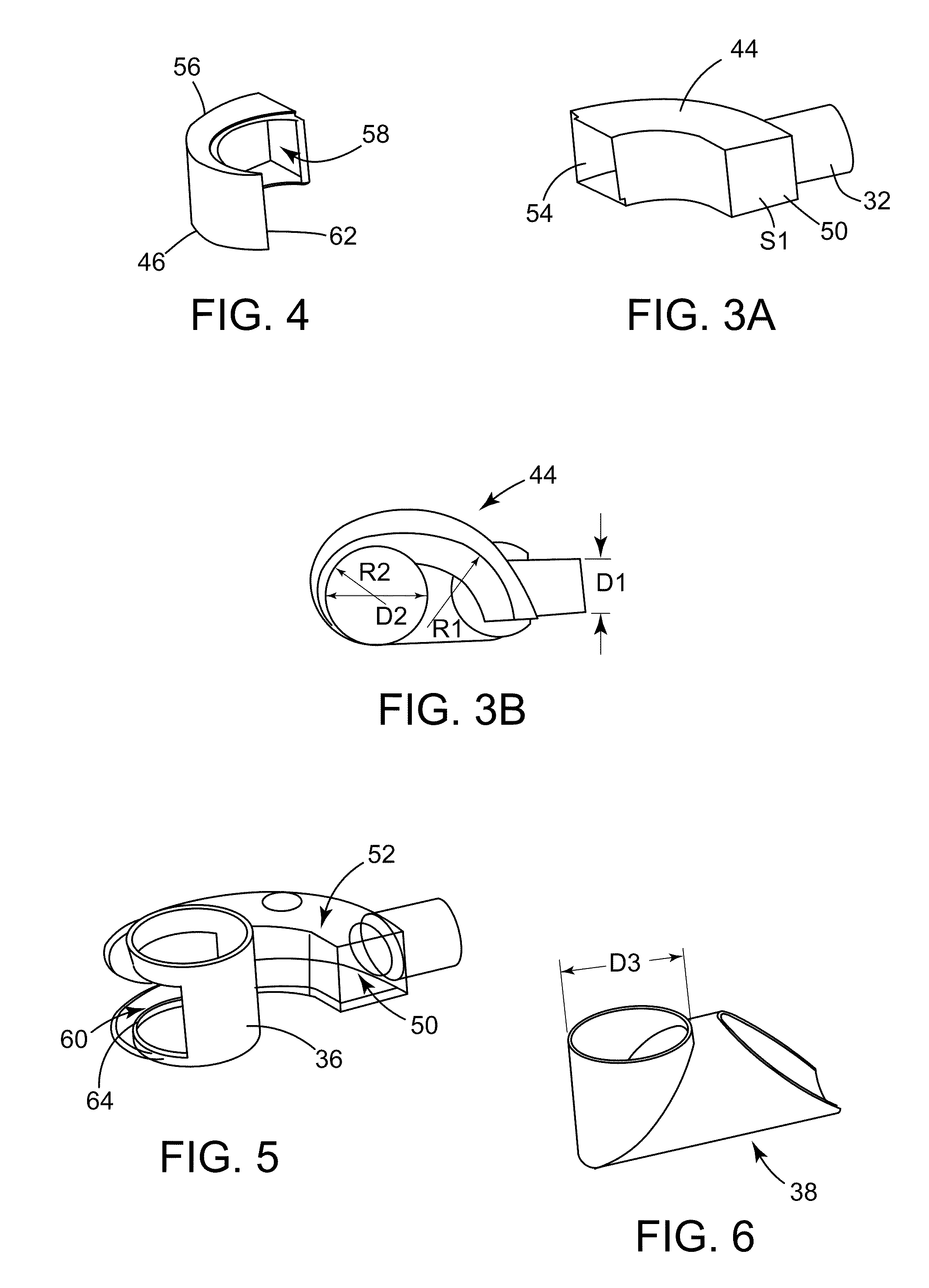
[0080]The simulations were conducted for a 45.5 meter long, 4.26 meter diameter, three-phase high-pressure production trap, with the configuration and dimensions for the conventional momentum breaker box 31 shown and described with reference to FIGS. 12B-12G, and configuration and dimensions for the apparatus 30 of the present invention shown described with reference to FIGS. 13B-13I. The computational results obtained are based on the flow properties in Table 1:

TABLE 1OILWATERGASFlow rate (bbl / day)180,00054,0002,366,000Density (Kg / m3)...


PUM

PropertyMeasurementUnit
Angleaaaaaaaaaa
Angleaaaaaaaaaa
Lengthaaaaaaaaaa

Abstract

Provided herein is a conditioning apparatus that includes a geometrical configuration having an inlet flow deceleration conduit and a cyclonic tube to effectuate both liquid-gas separation and droplet coalescence. The apparatus is typically positioned at the inlet of a separator vessel used for removing water and gas from extracted crude oil containing entrained water and gas. The apparatus promotes droplet coalescence and gas separation for mixed fluids flowing into an existing water and oil separation device.

Description

RELATED APPLICATIONS[0001]This application is related to and claims the benefit of United Stated Provisional Patent Application Ser. No. 61 / 323,140 filed on Apr. 12, 2010, which is incorporated by reference herein in its entirety.BACKGROUND OF THE INVENTION[0002]1. Field of the Invention[0003]This invention relates to an apparatus for separation of gas from gas-liquid mixtures and promoting droplet coalescence of different liquids in the gas-liquid mixture.[0004]2. Description of Related Art[0005]Liquid / gas separation and droplet coalescence are important aspects of crude oil processing, especially at the early stages of production from the well head. The main goal of separator vessels, typically located in a Gas Oil Separation Plant (“GOSP”), is to separate the fluids and obtain oil of satisfactory quality having reduced water and gas content. As the water cut increases, oil production from the separator vessel is adversely influenced.[0006]U.S. Pat. No. 2,228,401 describes a centr...

Claims


Application Information

Patent Timeline
IPC IPC(8): B01D19/00
CPCB01D17/0217B01D19/0057B01D19/0094B04C9/00B01D45/16B04C5/04B01D45/06
Inventor AKHRAS, ABDUL RAHMAN ZAFERVILAGINES, REGIS DIDIERSHARIFF, MAHER MAQBOOL
Owner SAUDI ARABIAN OIL CO
Why Eureka
Try Eureka