Recyling and reburning carbon dioxide in an energy efficient way

a carbon dioxide and energy-efficient technology, applied in the field of carbon dioxide emissions reduction systems and processes, can solve the problems of cost effectiveness, carbon dioxide conversion, hydrogen formation, etc., and achieve the effect of reducing the amount of coal required per kilowatt hour of power produced and vastly increasing the efficiency of the plan

Inactive Publication Date: 2011-10-13
JURANITCH JAMES CHARLES
View PDF5 Cites 4 Cited by
  • Summary
  • Abstract
  • Description
  • Claims
  • Application Information

AI Technical Summary

Benefits of technology

[0016]In embodiments of the invention where the plasma melter is a Europlasma plasma melter, the pressure swing absorber has a carbon dioxide output for producing CO2. A water gas shift reactor is arranged intermediate of the Europlasma plasma melter and the pressure swing absorber for converting syngas available at a syngas output of the Europlasma plasma melter to CO2+H2 and thereby enhancing methane conversion in the Sabatier reactor.
[0020]The plasma melter is provided in some embodiments of the invention with a metal output for providing reclaimed metals. Also, a glass output is provided for facilitating removal of silica based construction materials.
[0029]The ceramic foam Sabatier reactor is advantageously closely coupled to a reverse water gas shift reactor (RWGSR), or any other fuel-producing endothermic reactor. The close coupling of a sympathetic endothermic reaction is not required but increases the energy efficiency of the inventive process.
[0032]The primary desired output of this invention is methane CH4 and CO, which are to be reburned in this specific illustrative embodiment of the invention in a conventional coal power plant. Reclaimed metals and silica based construction materials are additionally produced by the InEnTec PEM. The carbon dioxide emitted by the coal power plant is thus continuously recycled, bringing its carbon foot print closer to zero and vastly increasing the plant's efficiency, thereby reducing the amount of coal required per kilowatt-hour of power produced.

Problems solved by technology

A key stumbling block in the conversion of carbon dioxide has been the formation of hydrogen in a cost effective and energy effective method.
Conventional electrolysis, although viable and well understood, is energy inefficient and produces a large carbon foot print.
Up until now they have been difficult to implement on a large scale due to their unique thermal characteristics.
A problem that has plagued large scale implementation of Sabatier reactors is that as the media temperature exceeds about 200° C. the conversion efficiency of the reactor quickly falls off.

Method used


Image

  • Recyling and reburning carbon dioxide in an energy efficient way
  • Recyling and reburning carbon dioxide in an energy efficient way
  • Recyling and reburning carbon dioxide in an energy efficient way

Examples


Embodiment Construction

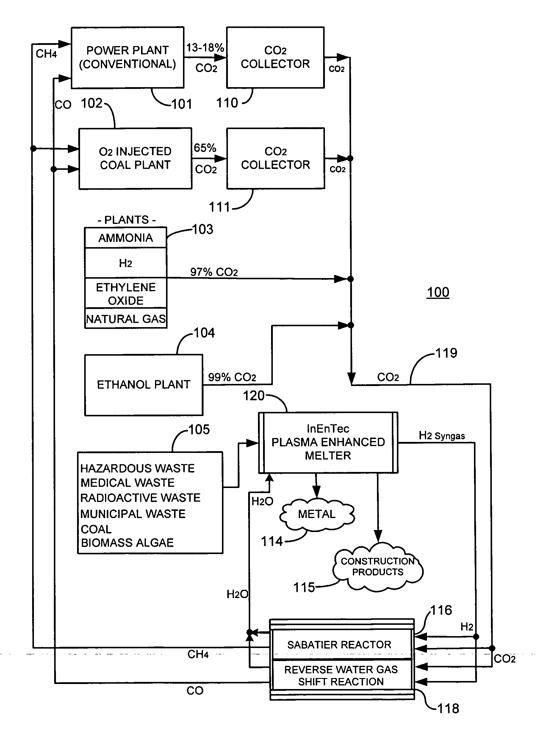
[0070]FIG. 1 is a simplified schematic representation of a specific illustrative embodiment of the invention. As shown in this figure, a carbon dioxide recycling system 100 includes a power plant 101, which in this embodiment of the invention is a conventional coal power plant having a base load, in this specific illustrative embodiment of the invention, of 1830 MW per day. In some embodiments of the invention, however, power plant 101 is powered by oil or natural gas. In embodiments where power plant 101 is a modern coal plant, it will emit on average about 3,458,700 Lbs of carbon dioxide per hour, or about 13 to 18% of its exhaust stream by volume.

[0071]Carbon dioxide recycling system 100 additionally is provided with an oxygen enriched coal power plant 102. Oxygen enriched coal power plant 102 issues a higher concentration of carbon dioxide in its exhaust stream, i.e., about 65% by volume. Other industrial plants 103 and 104 are also included in carbon dioxide recycling system 10...


PUM

PropertyMeasurementUnit
temperatureaaaaaaaaaa
energyaaaaaaaaaa
electrical poweraaaaaaaaaa

Abstract

A system for converting carbon dioxide into a fuel to be re-burned in an industrial process. The preferred feed stocks are taken from large volume carbon dioxide producers, and municipal waste. The reaction and processes reclaim lost energy in municipal waste, and industrial exhaust gas. The system is provided with a plasma melter having a feedstock input for receiving a feed fuel, and a syngas output for producing a syngas having an H2 component. Additionally, a Sabatier reactor is provided having a hydrogen input for receiving at least a portion of the H2 component produced by the plasma melter, and a methane output for producing CH4. The process has a large negative carbon footprint.

Description

RELATIONSHIP TO OTHER APPLICATIONS[0001]This application claims the benefit of the filing date of U.S. Provisional Patent Application Ser. No. 61 / 133,596 filed Jul. 1, 2008; and Provisional Patent Application Ser. No. 61 / 201,464 filed Dec. 10, 2008. The disclosures in the identified U.S. Provisional Patent Applications are incorporated herein by reference.BACKGROUND OF THE INVENTION[0002]1. Field of the Invention[0003]This invention relates generally to systems for reducing carbon emissions, and more particularly, to a system and process for reducing carbon dioxide emissions from power plants, particularly coal fired power plants.[0004]2. Description of the Prior Art[0005]In the current energy environment there is continuing pressure to produce more products and energy in a cost effective and clean way. Fuel prices continue to climb, and emission standards continue to tighten. Most of the modern world has attempted to limit the amount of carbon dioxide that is emitted into the atmos...

Claims


Application Information

Patent Timeline
Patent Type & Authority Applications(United States)
IPC IPC(8): B01J19/08C01B32/50
CPCC01B3/12C10J2300/1815C01B2203/0283C01B2203/043C01B2203/047C01B2203/0475C10J3/18C10J2300/0916C10J2300/093C10J2300/0946C10J2300/1238C10L3/08Y02E50/32C10J2300/1662C10J2300/1671C01B3/56Y02E50/30Y02P20/145
Inventor JURANITCH, JAMES CHARLES
Owner JURANITCH JAMES CHARLES
Why Eureka
Try Eureka