
System for tracking system properties

Inactive Publication Date: 2011-10-13
SMS DEMAG AG
View PDF19 Cites 13 Cited by
  • Summary
  • Abstract
  • Description
  • Claims
  • Application Information

AI Technical Summary

Benefits of technology

[0005]Therefore, it was an object of the invention to make available a device for the active monitoring of specific data in plants or their components of a steel works which, compared to the prior art, has a low susceptibility to errors and a low expenditure of man hours.
[0014]The central data storage as well as the central process control unit are preferably connected to control units of the material supply and / or the replacement part procurement and / or the production planning and / or the maintenance, in order to thereby advantageously increase the automation degree of the metallurgical plant or at least of parts thereof.
[0018]It is particularly preferred if the storage medium, which is fixedly connected to the component, as encapsulated relative to the surroundings, i.e., is preferably heat and moisture insulated. As a result, the use in metallurgical plants is particularly advantageously reinforced and a failure of the storage medium because of a contact with the harmful surrounding conditions frequently occurring in metallurgical plants is substantially avoided.
[0019]Particularly preferred is a wireless recording and reading capability of the storage medium, in particular by means of wireless transmissions in the microwave range. As a result, global as well as local communication paths are created between the RFID / microprocessor units and the individual components, the structural groups, plants or also with data bank systems which operate for all plants, as well as the connected internal or external maintenance and repair operations and / or firms for material and replacement part procurement and the production planning are significantly improved. It is then possible to communicate locally between the RFID-tags or microprocessor units integrated in the plant components and integrated stationary or mobile reading and writing units.

Problems solved by technology

Such data collection and follow up as well as maintenance of the data has been found to be especially time and cost consuming as well as to be subject to errors.

Method used


Image

  • System for tracking system properties
  • System for tracking system properties
  • System for tracking system properties

Examples


Embodiment Construction

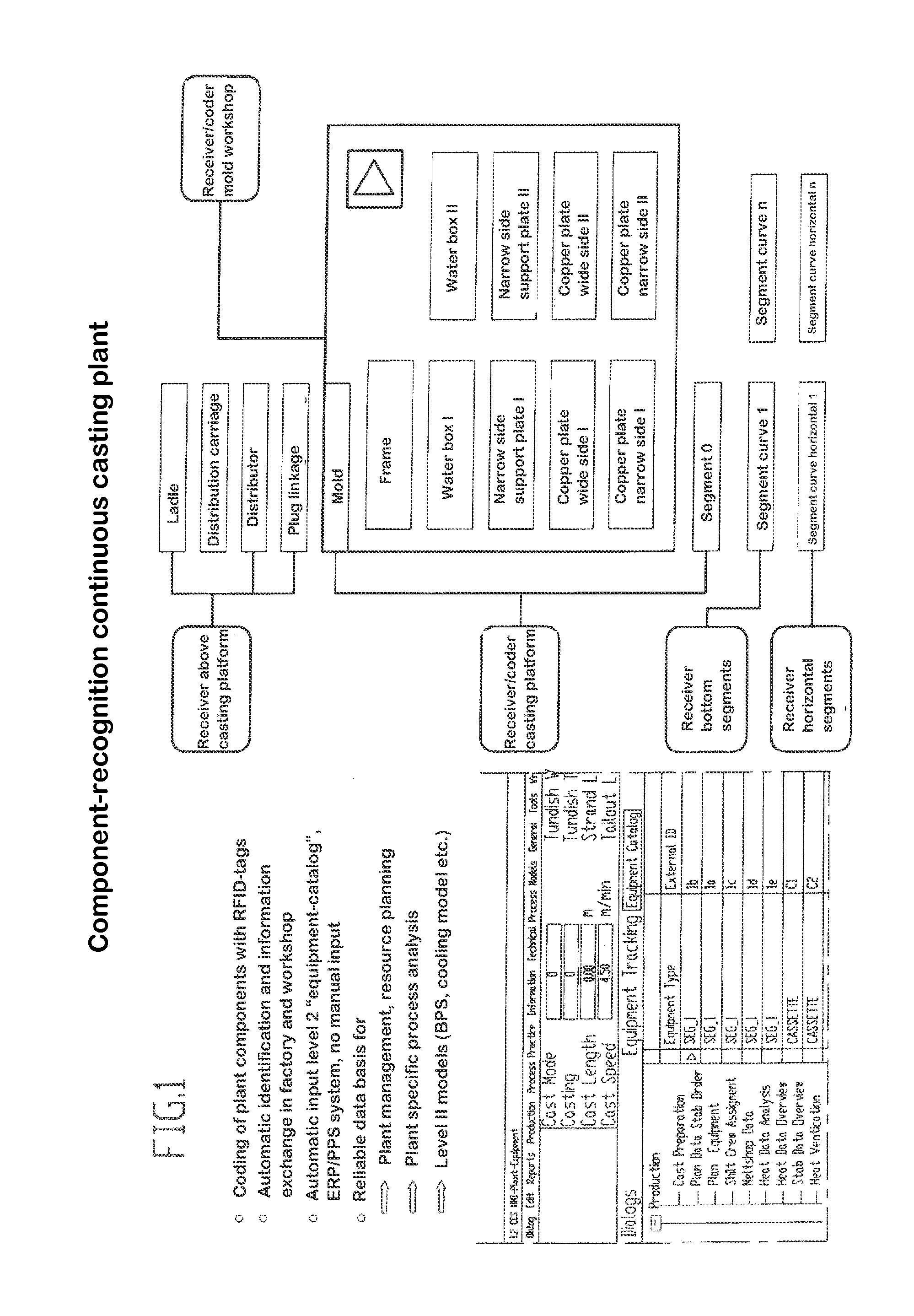
[0030]FIG. 1 shows as an example the component recognition according to the invention by means of an RFID-tag in a continuous casting plant and the automatic identification and the information exchange in factory and workshop. The RFID-tags connected to the individual components for the ladle, the distribution carriage, the distributor and the plug linkage are in communication with a receiver above the casting platform, while the RFID-tags for the mold, particularly the frame thereof, the various water boxes, the narrow side support plates, the copper plate wide sides and copper plate narrow sides are in communication with a receiver / coder in the mold workshop. The RFID-tags mentioned last and connected to the mold are together with RFID-tags additionally in communication with a receiver / coder on the casting platform at least at the first support segment underneath the mold. RFID-tags at the support segments in the curved portion of the strand guidance underneath the mold are in com...


PUM

PropertyMeasurementUnit
Mechanical propertiesaaaaaaaaaa
Physical propertiesaaaaaaaaaa

Abstract

The invention relates to a device for actively tracking specific data on systems or the components of a metallurgical system, characterized in that at least one readable and writable memory medium for the specific data is fixedly connected to each component, and the specific data are modifiable periodically and / or on the basis of input. In addition, the invention relates to a metallurgical system, in particular an integrated foundry or a mini-mill, comprising at least one device according to the invention. Finally, the invention relates to the use of at least one device according to the invention in an electric steel mill or a converter steel mill and / or in systems of secondary metallurgy and / or in casting plants, in particular continuous casting machines, and / or in molten steel transport units and / or in furnace systerms and / or in hot and cold rolling mills and / or in rolled stock treatment systems, in particular strip treatment systems.

Description

I. FIELD OF THE INVENTION[0001]The invention relates to a device for actively monitoring specific data concerning plants or their components in a metallurgical plant, particularly the use of such a device in an electric or converter steel mill, of secondary metallurgy or a casting plant, in liquid steel transport units or furnace plants, in hot and cold rolling plants or also strip treatment plants.II. State of the Art[0002]Metallurgical plants, such as integrated steel works or minimills, consist of a number of plants which in cooperation with each other have the object of producing a high quality product with the highest possible plant utilization. In the respective plant types of the total system, there are, in turn, structural groups, consisting of structural subgroups and individual components. Mentioned only as an example is a continuous casting plant which consists of a supply container for the liquid steel, a tundish, various stopping rods and immersed outlets, at least one ...

Claims


Application Information

Patent Timeline
IPC IPC(8): G06F19/00
CPCB22D11/14B22D11/16C21C2300/06C21C2005/5288C21C5/4673Y02P10/20Y02P10/25
Inventor SCHLUTER, JOCHENREIFFERSCHEID, MARKUSHULLEN, INA
Owner SMS DEMAG AG
Learn More