However, for many applications,
shot peening does not provide sufficiently intense or deep treatment, does not provide sufficient control of intensity or depth, or cannot be used because of its detrimental effect on the
surface finish.
This method becomes both costly and highly work piece specific, requiring considerable
engineering to develop processes for new work pieces.
In addition, work piece size is limited to the lifting and handling capacity of the
automation utilized.
However, there are a number of disadvantages to its design, including for example:1. The pointing accuracy of the
stinger depends on the
absolute accuracy of the
robot axes; particularly the axes in the
robot wrist.
This often results in errors in the spot pattern placement that must be manually corrected in a process that requires multiple iterations and can take hours, days, or even weeks in some instances.
Fortunately, once the pattern is established, the
robot motion is very consistent, usually making it unnecessary to repeat this alignment exercise so long at the work piece and robot remain stationary.2. The robot must reposition the
stinger on every laser pulse to point to a new spot on the work piece, making the
pulse repetition frequency (PRF) limited by the speed of the
robot motion.
However, the effectiveness of the approach mentioned there was limited by the small scanning range available, and would not be effective for complex surfaces.3. There is no
aspect ratio control to correct for spot elongation during off-axis
peening.
For small spot areas this can result in a
narrow beam foot print.
Since peening efficiency is better for larger spot dimensions that create a flatter wave front for the
shock wave induced in the
metal, the
narrow beam foot print reduces peening efficiency.4. Active
robot motion in the near proximity of a very valuable work piece can increase the possibility of a robot collision and damage to a customer part.5. The stand-off distance between the final optic of the
stinger and the treatment plane needs to be kept as short as possible to minimize the amount of
robot motion required to hit different non-parallel surfaces on the work piece at near normal incidence.6. The calibration of the energy and beam profile diagnostics built into the stinger is very sensitive to beam
depolarization in the
beam delivery path between the laser output and the stinger.7. There is limited polarization control.
A 90° quart rotator that can be moved in and out of the output beam by a pneumatic stage was used in later systems, but the polarization still could not be set to an arbitrary angle with respect to the work piece.
This increased the need for routine inspection and cleaning of the optical components since dust and debris on optical surfaces can lead to catastrophic
laser damage.
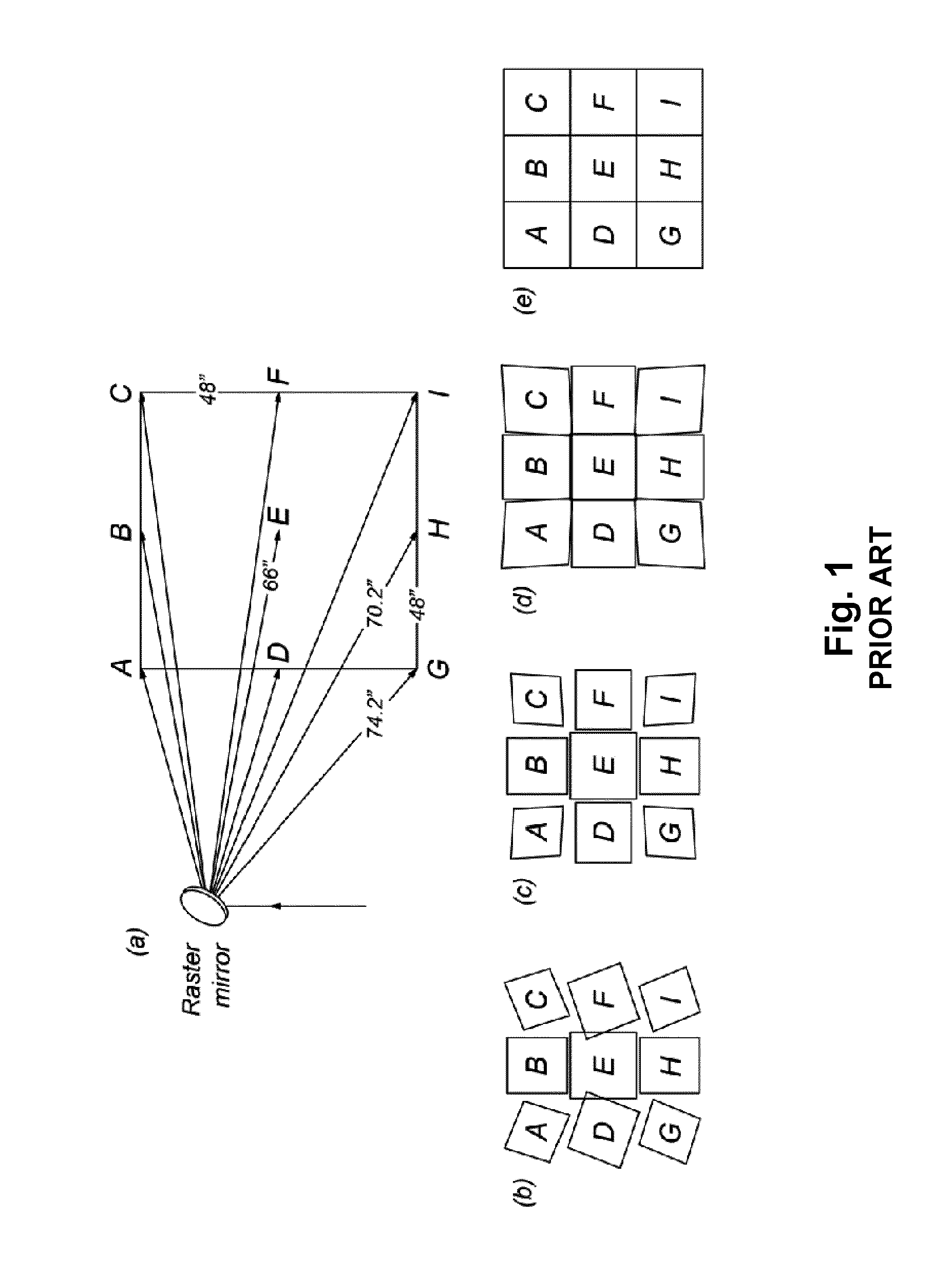
Using a single
gimbal position encounters problems because of the range of angles of incidence in the process area as the beam scanned over the area 4 feet on a side.
Thus, for the panel forming process, the challenge to overcome was how to maintain correctly located, rotated, shaped, and sized spots, independent of location on the panel.
Since the laser beam is converging on its way to the surface of the work piece, increasing propagation distance as the beam is pointed away from the center of the panel causes it to shrink.
However, it does not address the problems outlined above for implementation of a versatile
system usable with complex surface geometries encountered in industrial
laser peening systems.

