Method and apparatus for laser machining relatively narrow and relatively wide structures

a laser machining and structure technology, applied in laser beam welding apparatus, laser printed circuit aspects, electrical apparatus, etc., can solve the problems of reducing the efficiency of laser machining, affecting the accuracy of laser machining, so as to achieve the effect of increasing the energy density

Inactive Publication Date: 2011-10-27
M SOLV
View PDF2 Cites 72 Cited by
  • Summary
  • Abstract
  • Description
  • Claims
  • Application Information

AI Technical Summary

Benefits of technology

[0033]In general, the imaging optical system used de-magnifies the aperture or mask onto the substrate so that higher energy densities can be achieved on the substrate without risk of damage to the mask or aperture. Typical pad and via sizes are from a few 10s of microns up to a few 100s of microns in diameter. Typical aperture dimensions may be up to a few mm in diameter so demagnification ratios from a few to 10 or even more are generally used.

Problems solved by technology

However, because of the limited laser power available from highly focusable UV laser, this direct write process is slow when it comes to removing the more substantial volume of material associated with the larger area pads and contact holes.
This direct write method also has difficulty maintaining constant depth at the intersections between grooves and pads.
However, except in the case where the circuitry is extremely dense, this mask imaging is approach is significantly more costly than the direct write approach since the purchase and operating costs of excimer lasers are both very high.
Mask imaging is also very inflexible in that a new mask needs to be manufactured each time a new circuit design is required.
In addition, excimer laser mask projection is not well suited to creating structures of different depth as required especially for the contact holes.
This two step process is an effective way of dealing with the varying depth structure requirements but still suffers from the high cost and poor flexibility associated with the use of masks and excimer lasers.
Hence, it can be seen that the existing process methods for making advanced circuits based on this “laser-embedded circuit technology” have serious disadvantages.

Method used


Image

  • Method and apparatus for laser machining relatively narrow and relatively wide structures
  • Method and apparatus for laser machining relatively narrow and relatively wide structures
  • Method and apparatus for laser machining relatively narrow and relatively wide structures

Examples


Embodiment Construction
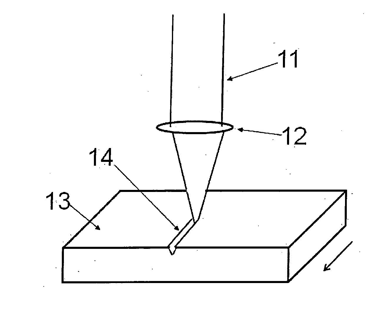
[0054]FIG. 1

[0055]FIG. 1 illustrates a process whereby a first laser beam is used to create fine grooves in the surface of a substrate 13. Laser beam 11 is of high quality having diffraction limited or close to diffraction limited properties. Lens 12 focuses the laser beam onto the surface of the substrate 13 to create a small spot. The energy absorbed causes the substrate material in the region of the focal spot to be vaporized. The laser beam is moved over the substrate surface so that a groove 14 is formed. A straight groove 14 is shown in the figure but in practice grooves can be of any shape set by the motion of the beam with respect to the substrate 13. Grooves can be of any length set by the limits of the mechanism that moves the beam with respect to the substrate. If the laser used is of CW type, then the depth of groove formed will be of uniform depth along its length so long as the laser power, beam size and speed are held constant. If the laser used is of pulsed type, the...


PUM

PropertyMeasurementUnit
wavelengthaaaaaaaaaa
widthaaaaaaaaaa
widthaaaaaaaaaa

Abstract

The method uses a common optical, system and sequentially creates structures of different sizes in a polymer substrate by means of different laser processes is described. One process uses a laser beam that is tightly focussed on the substrate surface and is used for creating fine groove structures by semi-continuous direct write type beam movement. The second process uses a second laser beam that is used to form a larger size image on the substrate surface and is used to create blind pads and contact holes in the substrate in step and drill mode. A third optional process uses the second laser beam operating in direct writing mode to remove layers of the substrate over larger continuous areas or in a mesh type pattern.

Description

TECHNICAL FIELD[0001]This invention relates to a method and apparatus for laser machining structures of different widths in a dielectric substrate. It is particularly relevant to the sequential formation of narrow groove or trench structures and larger area pad and blind contact holes and / or ground-plane structures in the top surface of a layer of polymer for the purpose manufacturing micro-electronic circuits.BACKGROUND ART[0002]Lasers are widely used in the manufacture of advanced printed circuit boards (PCBs). A particularly well known example is the drilling of blind contact holes, so called micro-vias, in multi layer PCBs. In this case ultra violet (UV) lasers are often used to drill through a top copper layer and an underlying dielectric layer to allow contact to, be made to a lower copper layer. In some cases, the cost effectiveness of this process is improved by using two different laser processes to remove the two different materials. A UV diode pumped solid state (DPSS) la...

Claims


Application Information

Patent Timeline
Patent Type & Authority Applications(United States)
IPC IPC(8): H05K1/11B23K26/40
CPCH05K2201/09036H05K3/107B23K26/0613Y10T29/49155B23K26/367B23K26/4065B23K26/063B23K26/0676B23K26/409H05K2203/108B23K26/0656B23K26/385H05K3/0032B23K26/0807B23K26/364B23K26/082B23K26/0622B23K26/066B23K26/40B23K26/389B23K2103/172B23K2103/42B23K2103/50
Inventor RUMSBY, PHILIP THOMAS
Owner M SOLV
Why Eureka
Try Eureka