Process for separating carbon dioxide from flue gas using sweep-based membrane separation and absorption steps
a technology of membrane separation and carbon dioxide, applied in separation processes, emission prevention, lighting and heating apparatus, etc., can solve the problems of power plants producing enormous amounts of flue gas, and achieve the effect of reducing the amount of co2
- Summary
- Abstract
- Description
- Claims
- Application Information
AI Technical Summary
Benefits of technology
Problems solved by technology
Method used
Image
Examples
example 1
Bases of Calculations for Other Examples
[0089](a) Membrane permeation experiments: The following calculations were performed using a composite membrane having a polyether-based selective layer with the properties shown in Table 1.
TABLE 1GasPermeance (gpu)*CO2 / Gas SelectivityCarbon dioxide1,000 —Nitrogen3033Oxygen6017Hydrogen100 10Water5,000** —*Gas permeation unit; 1 gpu = 1 × 10⁻⁶ cm3 (STP) / cm2 · s · cmHg**Estimated, not measured
[0090](b) Calculation methodology: All calculations were performed using a modeling program, ChemCad 5.6 (ChemStations, Inc., Houston, Tex.), containing code for the membrane operation developed by MTR's engineering group. For the calculations, all compressors and vacuum pumps were assumed to be 75% efficient. In each case, the modeling calculation was performed to achieve about 80-90% recovery of carbon dioxide from the flue gas stream.
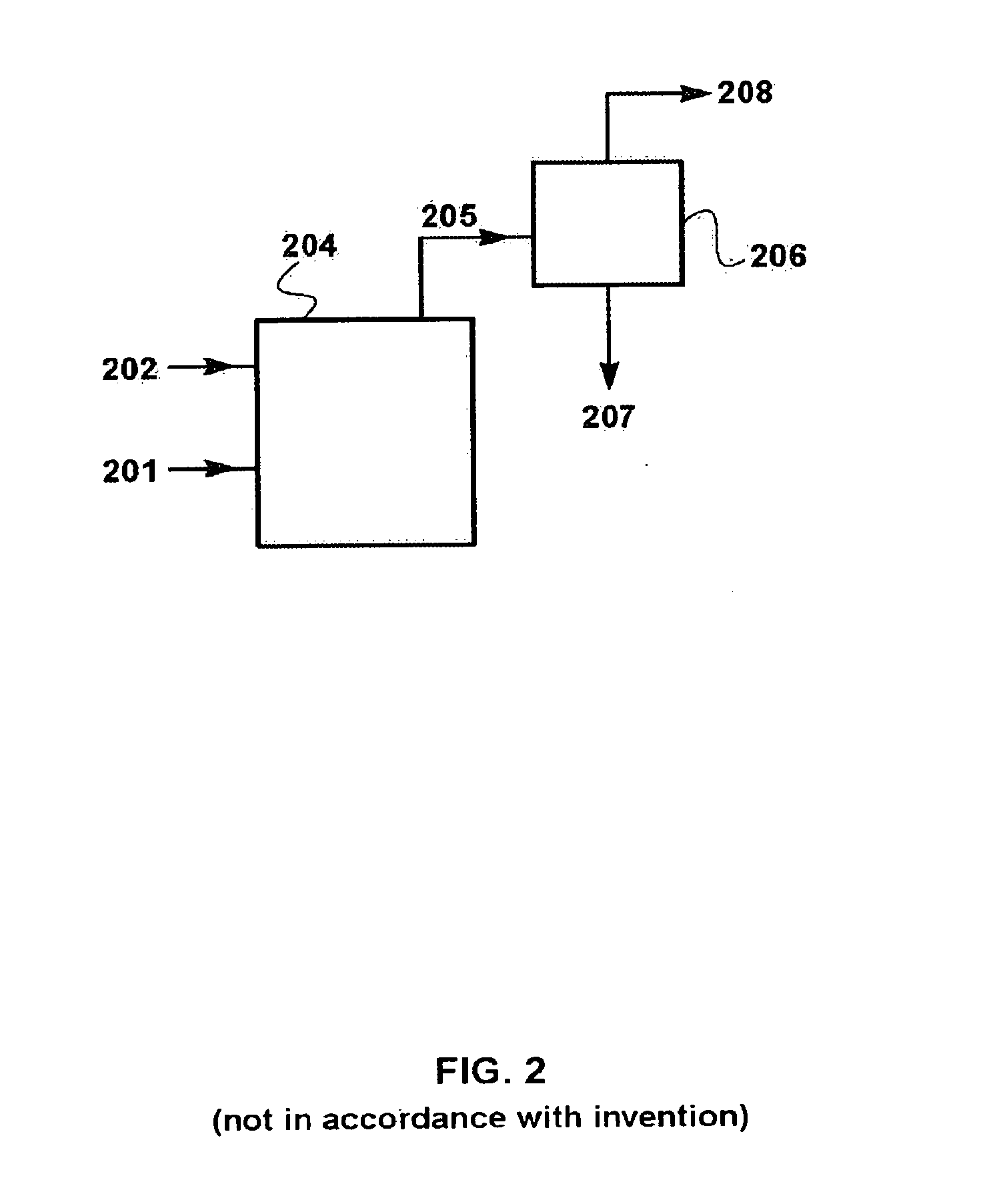
[0091]To facilitate operation of the calculation software, for Examples 1 through 3, the base case air flow provided to t...
example 2
Serial Carbon Dioxide Capture / Membrane Sweep (not in Accordance with the Invention)
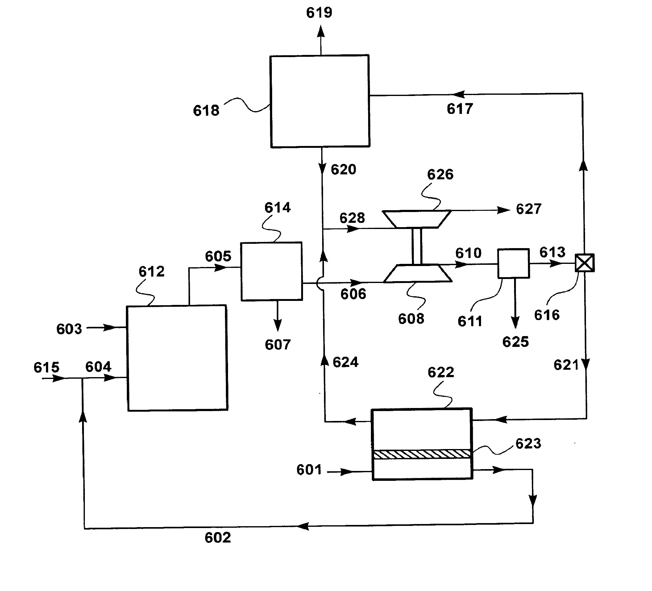
[0096]A computer calculation was performed to determine the chemical composition of exhaust gas from a coal combustion process, where an amine-based carbon dioxide capture step and the membrane-based separation step are performed serially. FIG. 3 is a schematic drawing of a flow scheme for such a serial combustion process.
[0097]Referring to FIG. 3, coal 303 and air stream 304 are introduced into combustion step or zone 312. Stream 304 is made up of recycled exhaust stream 302 and additional air or oxygen supply stream 315.
[0098]Combustion exhaust stream 305 is withdrawn, then routed through a condenser (not shown), where water is knocked out of the stream. The dehydrated exhaust stream 305 is then routed to an amine scrubbing plant 314, where carbon dioxide-rich stream 307 is withdrawn, and carbon dioxide-depleted stream 306 is routed to a sweep-based membrane separation step. The membrane separation ...
example 3
Process of the Invention
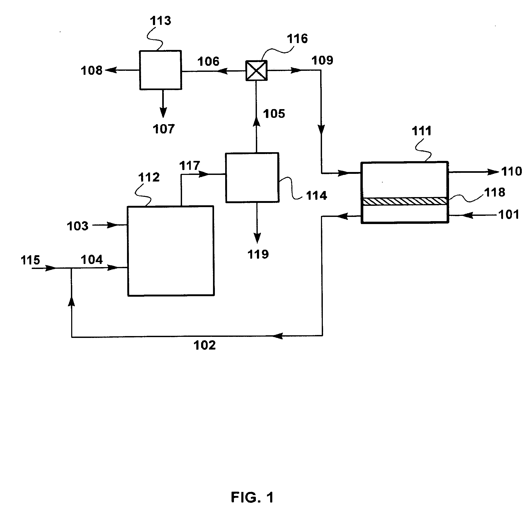
[0101]The calculations for this Example were performed using the flow scheme shown in FIG. 1 and described in the Detailed Description, above. This flow scheme includes an amine scrubbing step 113 performed in parallel with a sweep-based membrane separation step 111.
[0102]In this set of calculations, the membrane area was assumed to be 700 m2, and the combustion exhaust stream split was set at 1:1 (flow to carbon dioxide capture step:flow to sweep-based membrane separation step). Air flow 101 is 900 kg / h. The results of this calculation are shown in Table 4.
TABLE 4StreamAmineCO2Vent GasMembrane ResidueGas toPlantConcentrateFrom AmineMembraneTreated FlueAirCombustorCoalFeedStreamUnitFeedGas(101)(102)(103)(106)(107)(108)(109)(110)ParameterTotal Flow (kg / h)9001,07355561180372561378Temperature (° C.)2528253030253025Pressure (bar)1.01.01.01.01.01.01.01.0Component (vol %)Coal0010000000Oxygen21.016.502.302.12.37.4Nitrogen79.070.1070.70.192.070.791.8Carbon Dioxide011...
PUM
| Property | Measurement | Unit |
|---|---|---|
| Pressure | aaaaa | aaaaa |
| Volume | aaaaa | aaaaa |
| Fraction | aaaaa | aaaaa |
Abstract
Description
Claims
Application Information
 - R&D
- Intellectual Property
- Life Sciences
- Materials
- Tech Scout
- Unparalleled Data Quality
- Higher Quality Content
- 60% Fewer Hallucinations
Browse by: Latest US Patents, China's latest patents, Technical Efficacy Thesaurus, Application Domain, Technology Topic, Popular Technical Reports.
© 2025 PatSnap. All rights reserved.Legal|Privacy policy|Modern Slavery Act Transparency Statement|Sitemap|About US| Contact US: help@patsnap.com


