Thermal barrier coating material, thermal barrier coating, turbine member, and gas turbine

a technology of thermal barrier coating and thermal barrier coating, which is applied in the direction of metallic material coating process, machine/engine, blade accessories, etc., can solve the problems of dramatic deterioration in durability, loss of heat resistance, and inability to withstand the types of high temperature mentioned above, and achieve high degree of fracture toughness, excellent crystal stability, and low thermal conductivity

Inactive Publication Date: 2011-10-27
MITSUBISHI HEAVY IND LTD
View PDF13 Cites 7 Cited by
  • Summary
  • Abstract
  • Description
  • Claims
  • Application Information

AI Technical Summary

Benefits of technology

[0023]A thermal barrier coating material of the composition described above exhibits excellent crystal stability at high temperature, a high degree of fracture toughness and low thermal conductivity. Accordingly, a thermal barrier coating that exhibits excellent durability to heat cycling and a superior thermal barrier effect can be obtained.

Problems solved by technology

However, even though the material used for the turbine blades is a heat-resistant metal, it is unable to withstand the types of high temperature mentioned above.
In those cases where the moving blades and / or stationary blades of a gas turbine are coated with a thermal barrier coating material containing a ceramic layer composed of the above-mentioned YSZ, there is a possibility that portions of the ceramic layer may detach during operation of the gas turbine under severe operating conditions exceeding 1500° C., resulting in a loss of heat resistance.
Further, YSZ suffers from a destabilization phenomenon at temperatures exceeding 1200° C., resulting in a dramatic deterioration in the durability.

Method used


Image

  • Thermal barrier coating material, thermal barrier coating, turbine member, and gas turbine
  • Thermal barrier coating material, thermal barrier coating, turbine member, and gas turbine
  • Thermal barrier coating material, thermal barrier coating, turbine member, and gas turbine

Examples


example 1

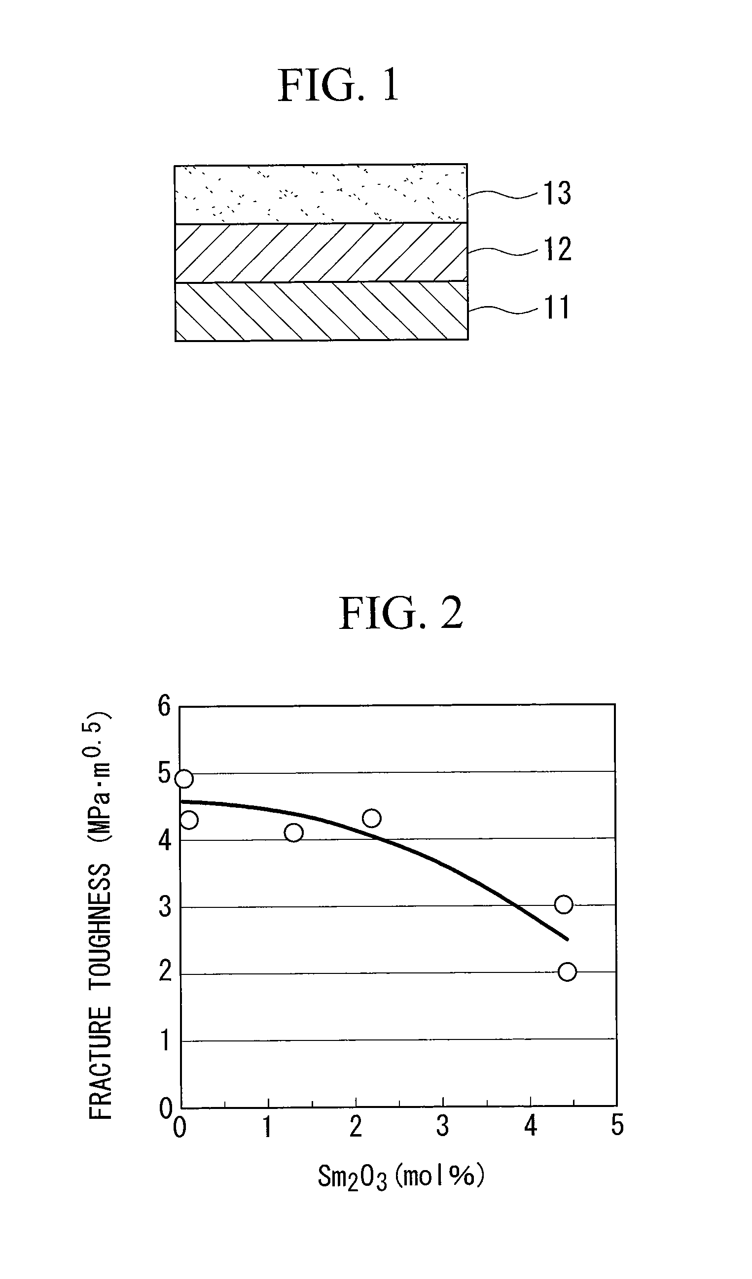
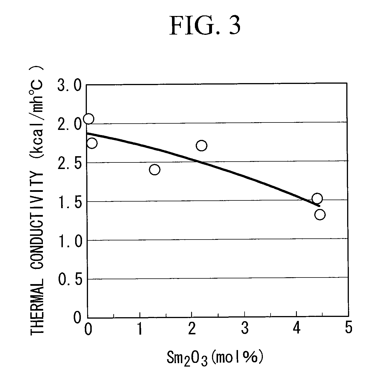
[0036]Sintered compacts of each of the compositions shown in Table 1 were prepared by pressureless sintering under conditions including a sintering temperature of 1600° C. and a sintering time of 5 hours. Yb2O3, Sm2O3 and ZrO2 were used as the raw material powders.

[0037]The fracture toughness value for each of the sintered compacts was measured in accordance with JIS R 1607. The thermal conductivity was measured using the laser flash method prescribed in JIS R 1611. The constituent phase of the sintered compact before and after heat treatment at 1300° C. for 1000 hours was identified by powder X-ray diffraction.

example 2

[0048]Using a spray dry process, spray powders having each of the compositions shown in Table 1 were prepared with particle sizes of 10 to 125 μm. Using these spray powders, test pieces with a thermal barrier coating formed thereon were prepared using the method outlined below.

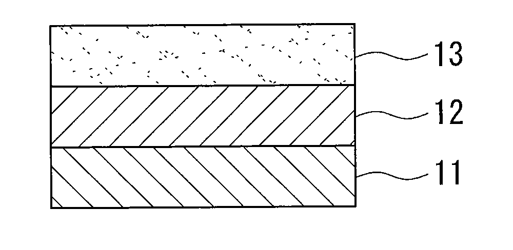
[0049]Using a low-pressure plasma spraying process, a metal bonding layer of thickness 100 μm was formed on an alloy metal substrate of thickness 5 mm (manufacturer: INCO Alloys International, Inc., trade name: IN-738LC, chemical composition: Ni-16Cr-8.5Co-1.75Mo-2.6W-1.75Ta-0.9Nb-3.4Ti-3.4Al (mass %)). The composition of the metal bonding layer was Ni: 32 mass %, Cr: 21 mass %, Al: 8 mass %, Y: 0.5 mass %, and Co: remainder.

[0050]Using atmospheric pressure plasma spraying, each of the above spray powders was sprayed onto the metal bonding layer, thus forming a sprayed coating (ceramic layer 13) having a thickness of 0.5 mm. A spray gun (F4 gun) manufactured by Sulzer Metco Ltd. was used for the spraying. The ...


PUM

PropertyMeasurementUnit
temperatureaaaaaaaaaa
temperaturesaaaaaaaaaa
surface temperatureaaaaaaaaaa

Abstract

A thermal barrier coating material that exhibits superior high-temperature crystal stability to YSZ, as well as a high degree of toughness and an excellent thermal barrier effect. Also provided are a thermal barrier coating, which has a ceramic layer formed using the thermal barrier coating material and exhibits excellent durability to heat cycling, and a turbine member and a gas turbine which are each provided with the thermal barrier coating. The thermal barrier coating material comprises mainly ZrO2 which contains Yb2O3 and Sm2O3 as stabilizers, wherein the amount of the stabilizers is not less than 2 mol % and not more than 7 mol %, and the amount of the Sm2O3 is not less than 0.1 mol % and not more than 2.5 mol %.

Description

TECHNICAL FIELD[0001]The present invention relates to a thermal barrier coating material having excellent durability, and relates particularly to a ceramic layer used as the top coat of a thermal barrier coating.BACKGROUND ART[0002]In recent years, enhancement of the thermal efficiency of thermal power generation has been investigated as a potential energy conservation measure. In order to enhance the electric power generation efficiency of a power-generating gas turbine, increasing the gas inlet temperature has been shown to be effective, and in some cases this temperature is increased to approximately 1500° C. In order to realize a power generation plant that can be operated at a higher temperature in this manner, the stationary blades and moving blades that constitute the gas turbine, and the walls of the combustor and the like must be formed of heat-resistant members. However, even though the material used for the turbine blades is a heat-resistant metal, it is unable to withsta...

Claims


Application Information

Patent Timeline
Patent Type & Authority Applications(United States)
IPC IPC(8): B32B15/04C04B35/48B32B18/00
CPCC04B35/486C04B2235/3224C04B2235/96C04B2235/9607C23C4/04Y10T428/12618F01D5/288F05D2230/90C23C28/3215C23C28/345C23C28/3455C23C4/105C23C4/11C23C26/00C23C4/10F01D5/28
Inventor TORIGOE, TAIJINAGANO, ICHIROOKADA, IKUOTSUKAGOSHI, KEIZOTAKAHASHI, KOJIOKAJIMA, YOSHIFUMIKASUMI, SOJIITO, EISAKUMORI, KAZUTAKA
Owner MITSUBISHI HEAVY IND LTD
Why Eureka
Try Eureka