

Sealants and conductive busbars for chromogenic devices
a technology of conductive busbars and sealing pads, which is applied in the direction of applications, manufacturing tools, instruments, etc., can solve the problems of contaminating the environment, high cost of adhesives, etc., and achieve the effects of reducing cost, increasing performance, and ensuring the environmen
- Summary
- Abstract
- Description
- Claims
- Application Information
AI Technical Summary
Benefits of technology
Problems solved by technology
Method used
Image

Examples
embodiment 1
Busbars for Electrooptic Devices
[0027]With the increased numbers of variable reflectance mirrors being used, there is a correspondingly increased desire to provide an environmentally improved variable reflectance mirror design. Millions of mirrors are being produced annually that incorporate variable reflectance elements with the above mentioned components. As an example U.S. Pat. No. 6,899,437 addresses this issue and this patent is herein incorporated in its entirety by reference. As discussed below this patent recognizes elements such as cadmium, mercury and lead and some compounds having chlorine, bromine and antimony as threats to the environment. However, this does not recognize threats caused by beryllium. Further, U.S. Pat. No. 6,899,437 takes the European directive 2002 / 95 / EG, “Restrictions pertaining to the use of certain Hazardous Substances” (RoHS) and translates them into claims without providing any new initiative on environmental friendliness. Many countries such as J...
embodiment 2
Perimeter Sealants
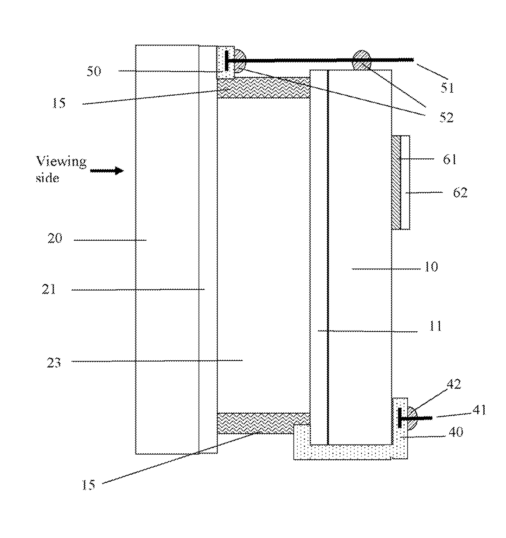
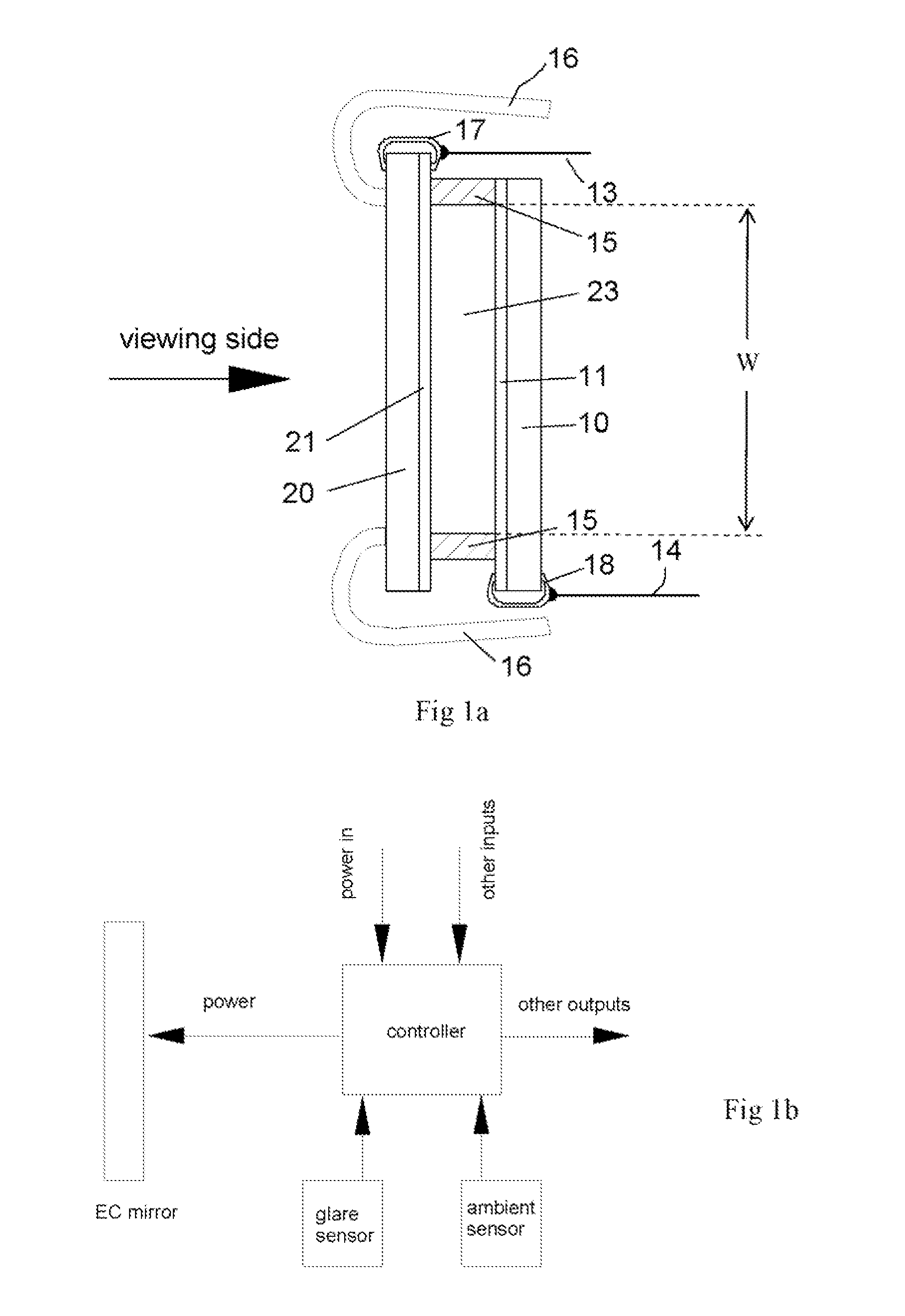
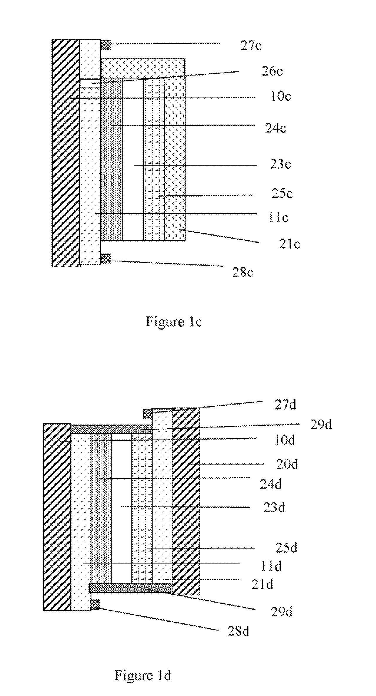
[0051]Epoxy adhesives are most commonly used as perimeter sealants in EC devices (perimeter sealant is shown as 15 in FIGS. 1, 2a and 4; and as 31 and 33 in FIGS. 3a; and as 31b and 33b in FIGS. 3b; and as 31c and 33c in FIG. 3c. Such sealants are well described in many US patents, such as U.S. Pat. Nos. 5,724,187; 7,064,882 and 7,738,155. These use epoxy resin formulations based on Bisphenol A, Bisphenol F, novalacs and other epoxies, and the curing agents are usually selected from amines (usually aromatic and cycloaliphatic), anhydride and catalytic cure systems. None of these describe additives to the epoxy resins that result in formation of a second phase upon curing of this epoxy. These additives improve adhesion and the joint toughness (e.g. see Bascom, W. D., et al, Journal of Applied Polymer Science, Vol. 19, 2545-2562 (1975)). To improve the toughness of the brittle epoxies, one adds a material which has different mechanical properties (particularly elasto...
embodiment 3
Transparent Conductors
[0053]The commercial EC devices use indium-tin oxide (ITO) or fluorine doped tin (FTO) oxide as transparent conductors (TC). Further, in the same device either the same composition or two different compositions of TC may be used. As an example, in third surface mirrors (see U.S. Pat. No. 7,300,166), the TC coating on surface 2 (the front substrate) may be ITO, and on surface 3 (rear substrate) a reflector coating is followed by a conductive passivation layer (against chemical and electrochemical corrosion) that may be doped zinc oxide (e.g., AZO or aluminum doped zinc oxide and magnesium doped zinc oxide, in oxide TCs, the metal dopants are also in the oxide forms) or antimony doped tin oxide. The conductivity of this TC layer may not be high, as the metal below provides sufficient conductivity. Due to the scarcity of indium, substitutes for ITO are being sought, and particularly these new TCs are targeting markets for solar cells and displays. Some of the emer...
PUM
| Property | Measurement | Unit |
|---|---|---|
| Percent by mass | aaaaa | aaaaa |
| Size | aaaaa | aaaaa |
| Temperature | aaaaa | aaaaa |
Abstract
Description
Claims
Application Information