[0036]The
Molten salt of this invention as catalyst comprises alkaline metal
hydroxide such as NaOH and KOH or
alkaline earth metal hydroxide such as Ba(OH)2 and Sr(OH)2, a first metal element (Ni, Pd or Pt) for
cutting the combination of hydrogen and oxygen and a second metal element (Cr, Mo, W, Fe, Co, Cu or Rh) for helping the function of the first metal element. The mixture of the hydroxide and the first and second metal elements is heated at a temperature above the
melting point of the hydroxide to separate hydrogen from oxygen. That is, the catalyst can operate at a temperature above 300° C. and, however, a
continuous operation needs at approximately 500° C. The catalyst does not cause a simple oxidizing reaction but an electrical and
chemical reaction or an ionizing reaction. In addition, a main reaction is caused by fine particles ejected from the liquid surface of the catalyst to enlarge remarkably a reaction surface area, and the
life span of the catalyst is long (over 3 months). Further, much water can be divided into hydrogen and oxygen at a low temperature.
[0037]In the case of
solid catalyst, a reaction for resolving water is the same as that of the liquid catalyst, its
reaction temperature is slightly higher than that of liquid catalyst. It is preferable to use
solid catalyst in case that a catalyst unit is swung in ships and automobiles.
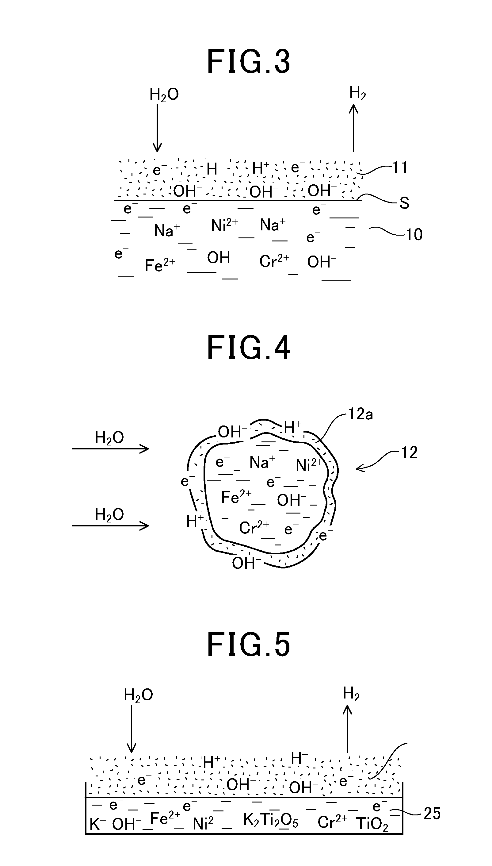
[0038]In the method of generating hydrogen according to this invention,
molten salt itself is ionized together with a metal element for
cutting the combination of hydrogen, and there are a lot of electrons in the
molten salt. Therefore, the fine particles dispersed from the liquid surface react on steam to ionize it thereby to produce a lot of hydrogen at a low temperature because of a remarkable largeness of reaction surface area. In addition, oxygen separated from hydrogen makes
oxide, a part of which can make up for the catalyst after reacting on steam and its remains flow out. Therefore, the catalyst
cell is not full of oxide to extend the
life span of the catalyst.
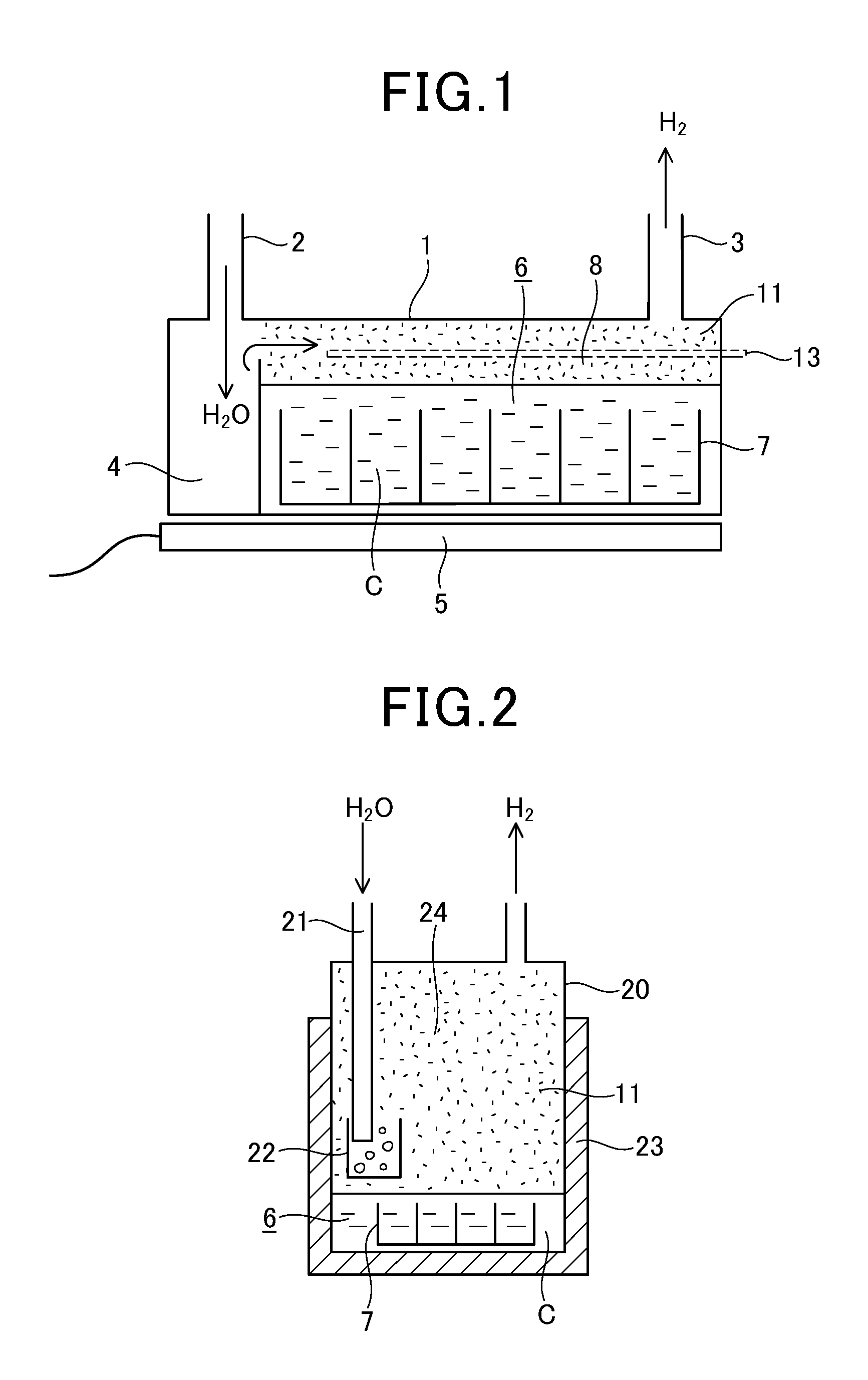
[0039]In the apparatus for generating hydrogen according to this invention, there are provided the catalyst
cell having
corrosion resistance, the steam producing portion, the metal element supply body including the case of the catalyst
cell, the heating device for heating the catalyst, and the air inflow prevention device for preventing air from flowing into the catalyst cell, and, therefore, the catalyst can have a long life span with a simple structure. Further, since the steam producing portion is formed in the catalyst cell, the portion and the catalyst can be heated by a single heating device to make the structure of the apparatus simple. And if the catalyst cell itself has the same function as that of the metal element supply body, the fins are unnecessary.
[0040]A water tank as the steam
elimination device has a function as the air inflow prevention device, and, therefore, the numbers of necessary members can be decreased.
[0041]Further, a vertical type of catalyst cell is, at its circumferential wall, heated by the plate-shaped heater, and, therefore, the reaction space formed at the upper portion of the catalyst cell can be effectively heated.

