Batteries, fuel cells, and other electrochemical devices

a fuel cell and electrochemical device technology, applied in the field of batteries, can solve the problems of affecting the output of the device performance may be affected, etc., and achieve the effects of improving the performance of the electrochemical device, enhancing the ion conductivity, and enhancing the heat transfer and turbulence of the reactan

Active Publication Date: 2011-11-10
GAS TECH INST
View PDF7 Cites 29 Cited by
  • Summary
  • Abstract
  • Description
  • Claims
  • Application Information

AI Technical Summary

Benefits of technology

[0008]Generally, it is an object of this invention to improve the performance of electrochemical devices such as batteries, fuel cells, biofuel cells, and the like.
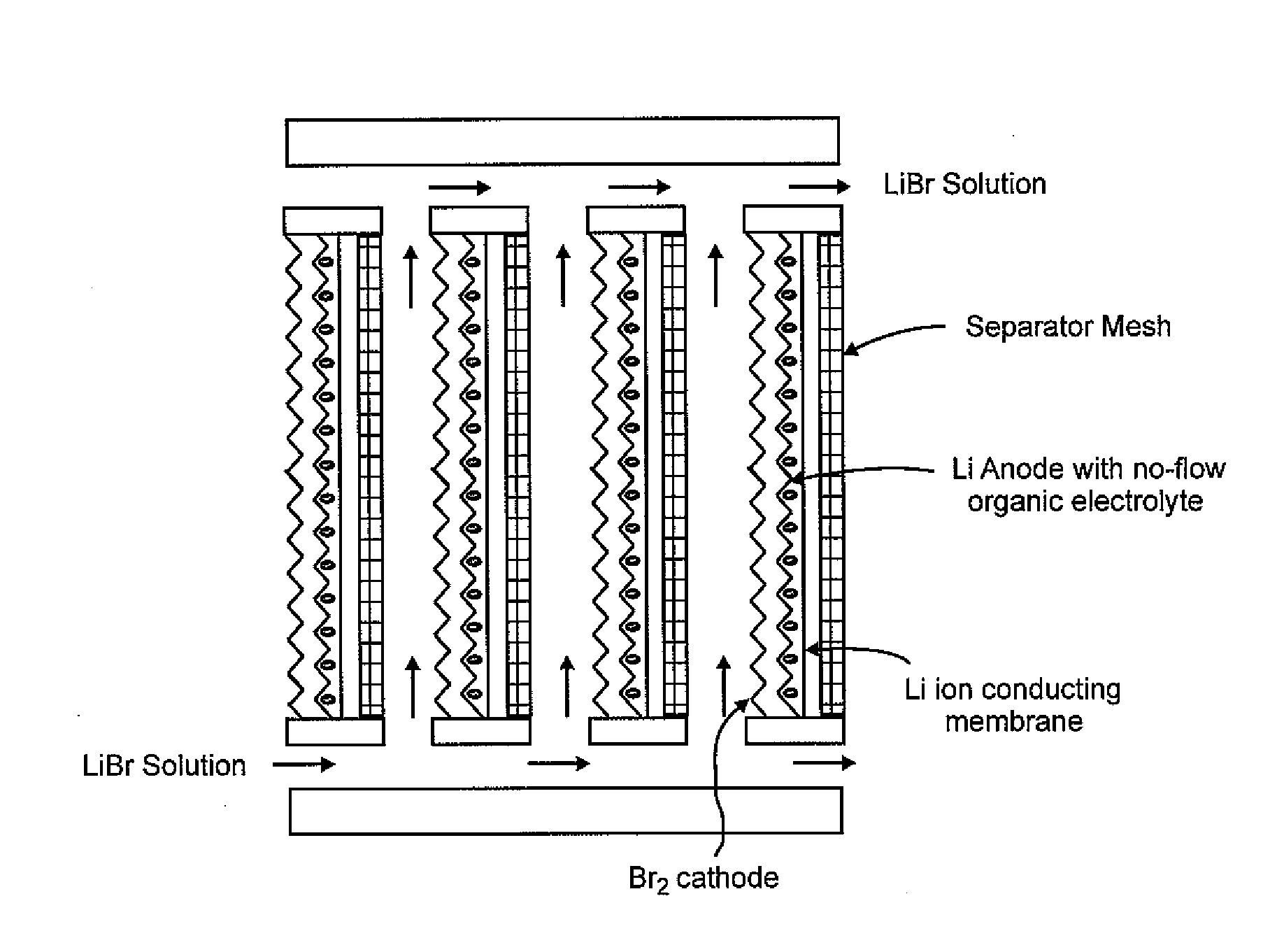
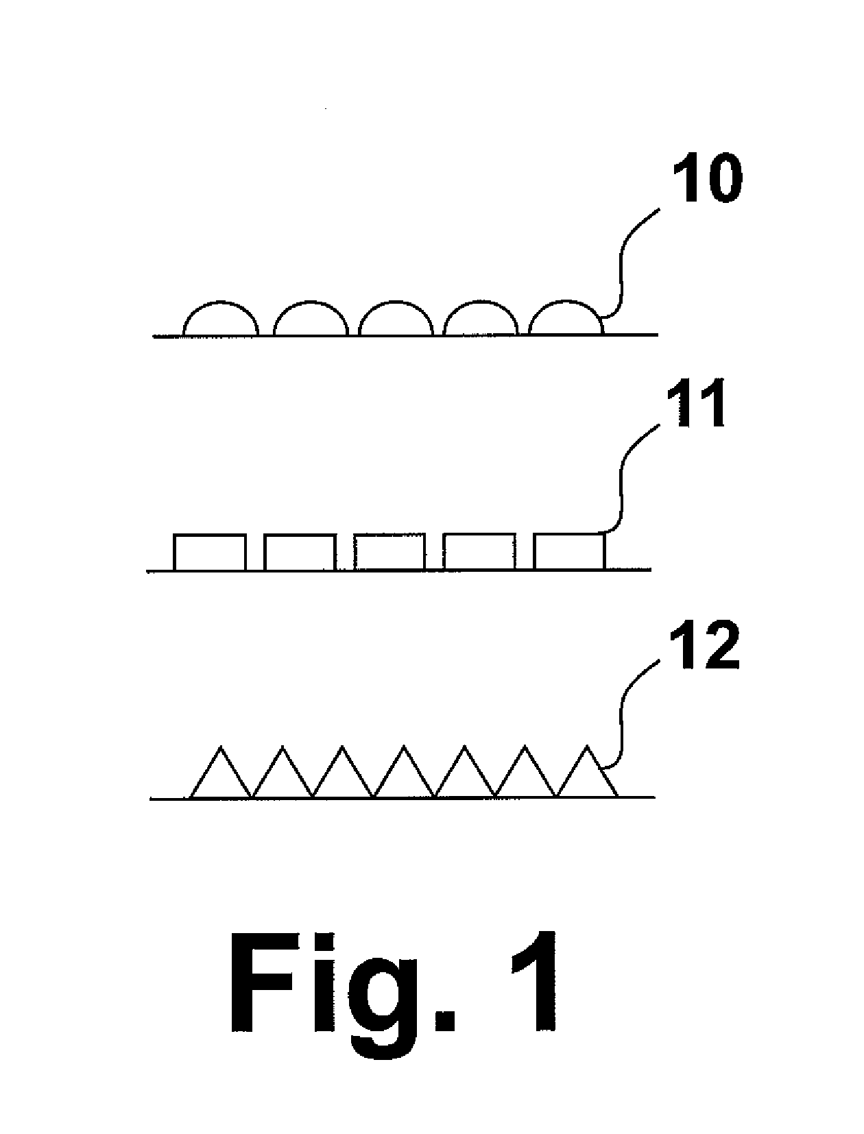
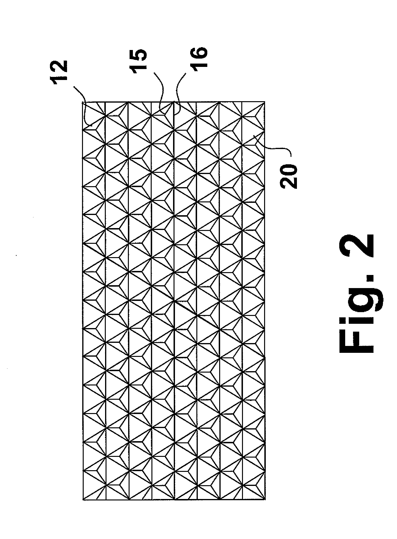
[0009]This and other objects of this invention are addressed by an electrochemical device comprising an anode electrode, a cathode electrode, and an electrolyte in which at least one of the anode electrode and the cathode electrode comprises a substantially uniform superficial relief pattern formed by a plurality of substantially uniform raised structures or projections having an electrical conductivity gradient between peaks of the raised structures and valleys between the raised structures, where the electrical conductivity is lower at the peaks than in the valleys. Conventional electrochemical devices typically employ components having substantially smooth surfaces. The raised structures may be semi-spherical, semi-elliptical, polyhedral or combinations thereof. Particularly preferred are raised structures having a tetrahedral shape. Such raised structures provide substantial increases in component surface areas compared with conventional electrochemical device components, thereby enhancing ion conductivity, heat transfer and turbulence of the reactants. In electrochemical devices employing a separator between the anode and cathode electrodes, the separator may also be provided with such raised structures so as to enhance separator performance. In electrochemical devices in which the electrolyte is a solid, the solid electrolyte may also be provided with such raised structures.

Problems solved by technology

For example, the amount of surface area available on the electrodes for reactions may affect reaction rates which, in turn, may affect the output of the device.
In some electrochemical devices, performance may be affected by the ability of the reactants to mix.
In some electrochemical devices, performance may be affected by the ability to control heat generated by the device.

Method used


Image

  • Batteries, fuel cells, and other electrochemical devices
  • Batteries, fuel cells, and other electrochemical devices
  • Batteries, fuel cells, and other electrochemical devices

Examples


example

[0027]In this example, a li-ion conducting solid comprising 14Li2O; 9Al2O3; 38 TiO2: 39 P2O is produced by mixing 6.2 g Li2CO3, 5.51 g Al2O3, 18.21 g TiO2, and 53.83 g NH4H2PO4 placing the mixture in an alumina crucible and melting the mixture in a furnace. The mixture is initially heated to 450° C. at a heating rate of 4.8° C. / min and held at that temperature for 1 hour to release gaseous components. The mixture is then heated to 1450° C. at a heating rate of 5° C. / min and melted for 1.5 hours. The resulting melt is poured into ice water, producing a crystallized glass-ceramic material. Subsequently, this crystallized glass-ceramic material is crushed into chunks and powdered.

[0028]The powdered material was mixed with high density polyethylene powder to make a blend of 75 wt % Li glass-ceramic, 25 wt % polyethylene. This material was then placed in a 2.25″ diameter stainless steel die and hot pressed at 15,000 lbs and 400° F. The pressure was applied for 30 minutes to ensure that t...


PUM

PropertyMeasurementUnit
thicknessaaaaaaaaaa
weightaaaaaaaaaa
weightaaaaaaaaaa

Abstract

An electrochemical device having an anode electrode, a cathode electrode, and an electrolyte. At least one of the anode electrode and the cathode electrode is provided with a substantially uniform superficial relief pattern formed by a plurality of substantially uniform projections and has an electrical conductivity gradient between peaks of the projections and valleys between the projections

Description

BACKGROUND OF THE INVENTION[0001]1. Field of the Invention[0002]This invention relates to electrochemical devices and components thereof. In one aspect, this invention relates to batteries. In one aspect, this invention relates to fuel cells. In one aspect, this invention relates to non-rechargeable batteries. In one aspect, this invention relates to rechargeable batteries. In one aspect, this invention relates to metal-air batteries. In one aspect, this invention relates to Li—Br2 batteries. In one aspect, this invention relates to LiBr flow batteries.[0003]2. Description of Related Art[0004]Electrochemistry is a branch of chemistry which involves the study of chemical reactions which take place in a solution at the interface of an electron conductor (a metal or a semiconductor) and ionic conductor (the electrolyte), and which involves electron transfer between the electrode and the electrolyte or species in solution. Chemical reactions driven by an external applied voltage, as in ...

Claims


Application Information

Patent Timeline
Patent Type & Authority Applications(United States)
IPC IPC(8): H01M8/22H01M4/583H01M2/16H01M4/02H01M8/16H01M50/463H01M50/77
CPCH01M2/18H01M4/13H01M4/366H01M4/622H01M4/8605H01M4/8615Y02E60/528H01M10/052H01M10/058H01M2004/029H01M2300/0054H01M2300/0082Y02E60/122H01M8/188Y02E60/50Y02E60/10H01M50/463
Inventor FAN, QINBAISTANIS, RONALD
Owner GAS TECH INST
Why Eureka
Try Eureka