Apparatus and method of optimized acid gas and toxic metal control in gasifier produced gases

a technology of acid gas and toxic metals, which is applied in the direction of combustible gas production, combustible gas purification/modification, and separation processes, etc. it can solve the problems of large contact volume, inability to effectively utilize sorbent, and inability to achieve the effect of reducing the number of sorbents, reducing the efficiency of sorbent utilization, and less than ideal sorbent performan

Active Publication Date: 2011-11-17
FRONTLINE BIOENERGY
View PDF3 Cites 10 Cited by
  • Summary
  • Abstract
  • Description
  • Claims
  • Application Information

AI Technical Summary

Benefits of technology

[0017]Alternate configurations of the apparatus could include additional stages of heat exchangers and gas-sorbent contact chambers or zones. Other configurations could also include gas-sorbent contact chambers or zones with integrated cooling stages to create optimum temperature gradients in the direction of flow. Optimizing temperature gradients would maximize acid gas uptake for a given reactor volume.
[0022]The fluid bed gasifier generates a gas product in an agitated bed of sand where the majority of the solids mass and temperatures generally exceed 700° C., and thus has an unfavorable equilibrium for chloride uptake. Counter intuitively, feeding powdered sorbent into the fluid bed results in a less effective utilization of the sorbent—a powdered sorbent injected to the fluid bed produces agglomerates that sink and are discharged as oversize solids from the fluid bed media screen. If fine sorbent is fed to the fluid bed it does not provide the opportunity to elutriate the preferred particle size with grinding during activation, as is the case with the present invention, because of a tendency of the powdered feed to form agglomerates. Injecting finely divided dry powders into the freeboard results in poor distribution of the sorbent, which limits its effectiveness. In contrast, feeding larger granular sorbent particles—especially when fed in higher frequency pulses (for example, more than ten injections per hour) will provide regular release through attrition of finely divided particles, highly dispersed and well mixed with the gas, and moreover, heat-activated particles that give the highest sorbent utilization.
[0023]Fluid bed reactors are commonly operated at atmospheric pressure in circulating mode (higher velocity by design that is on the order of 10 to 20 times the minimum fluidization velocity and that employs a cyclone for sand recovery), or bubbling mode (lower velocity by design, on the order of 3 to 8 times the minimum fluidization velocity). A fluid bed may also be operated at pressure. The elutriation rate and particle size of char-ash products of gasification and injected granular sorbent will vary with fluid bed velocity. By controlling the fluid bed pressure (by modulating input oxidant flow or by modulating a downstream pressure regulating valve) it is possible to control the fluid bed discharge velocity, and so controlling the sorbent and char-ash particle size is possible to a degree by controlling the fluid bed velocity.
[0024]In this invention, a fluid bed reactor is designed to operate at variable pressure to provide for a new degree of freedom—otherwise not available to atmospheric fluid bed gasifiers—for controlling the sorbent and bio-char particle size and release rate by correlating with bubbling fluid bed superficial velocity for production of activated and internally ground particles that were initially fed as larger granular materials. Pressurized operation also reduces the lower limit of concentration (the gas-phase HCl equilibrium mole fraction) that can be achieved compared to atmospheric pressure operation.

Problems solved by technology

However, some of these fuels (especially rapid growing biomass and RDF) contains chlorine and other contaminants.
Use of refuse derived fuels can also produce vapors of toxic metals if present in the waste feedstock, for example, mercury and lead.
This method operates at relatively lower temperatures and so requires large contact volumes.
However, injecting cold non-activated powders requires additional time for the powder to be warmed to the gas temperature.
These other disclosures do not achieve the quality of particle dispersion that might increase the efficiency of the process.
The circulating fluid bed relies on the sand recovery cyclone efficiency to influence particle slip; therefore, because the cyclone has a fixed geometry it cannot modulate with gas production capacity to effect any benefit for controlling sorbent and bio-char particle size with gas production capacity.
Moreover, the atmospheric system cannot modulate any parameter with capacity to maintain ideal superficial velocity for sorbent particle size quality, nor maintain downstream residence time as constant.
These systems must vary velocity with gas production capacity and therefore cannot modulate to achieve optimum particle size quality with varied gas production rates.
This is especially true when the system employs circulating fluid beds with fixed geometry cyclones that define the sorbent slip rate and the residence time in downstream sorbent contacting vessels and filters cannot be controlled.
Those systems therefore have less than ideal sorbent performance with gas production rate turndown.
The fluid bed gasifier generates a gas product in an agitated bed of sand where the majority of the solids mass and temperatures generally exceed 700° C., and thus has an unfavorable equilibrium for chloride uptake.
Counter intuitively, feeding powdered sorbent into the fluid bed results in a less effective utilization of the sorbent—a powdered sorbent injected to the fluid bed produces agglomerates that sink and are discharged as oversize solids from the fluid bed media screen.
Injecting finely divided dry powders into the freeboard results in poor distribution of the sorbent, which limits its effectiveness.

Method used


Image

  • Apparatus and method of optimized acid gas and toxic metal control in gasifier produced gases
  • Apparatus and method of optimized acid gas and toxic metal control in gasifier produced gases
  • Apparatus and method of optimized acid gas and toxic metal control in gasifier produced gases

Examples


example 1

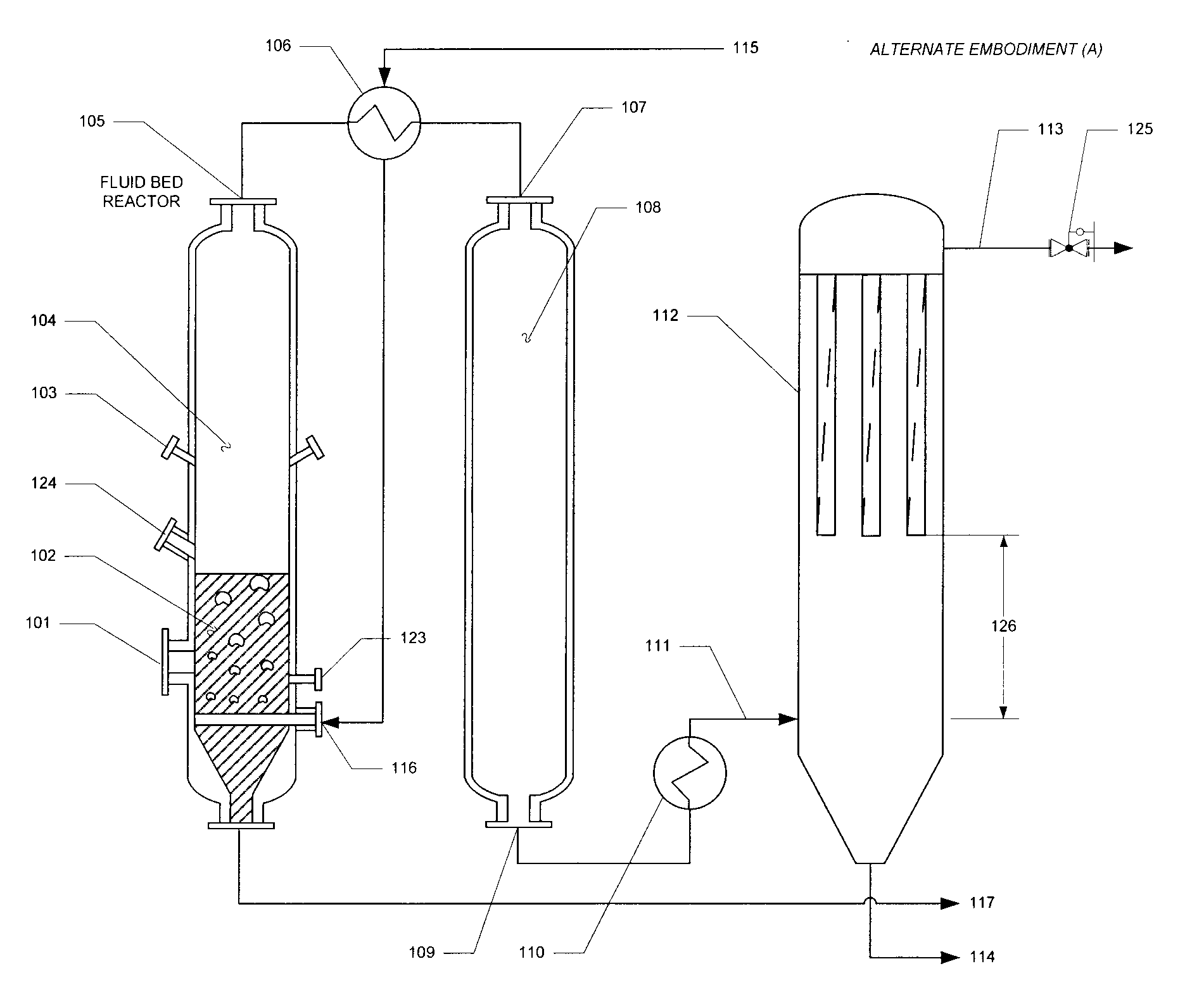
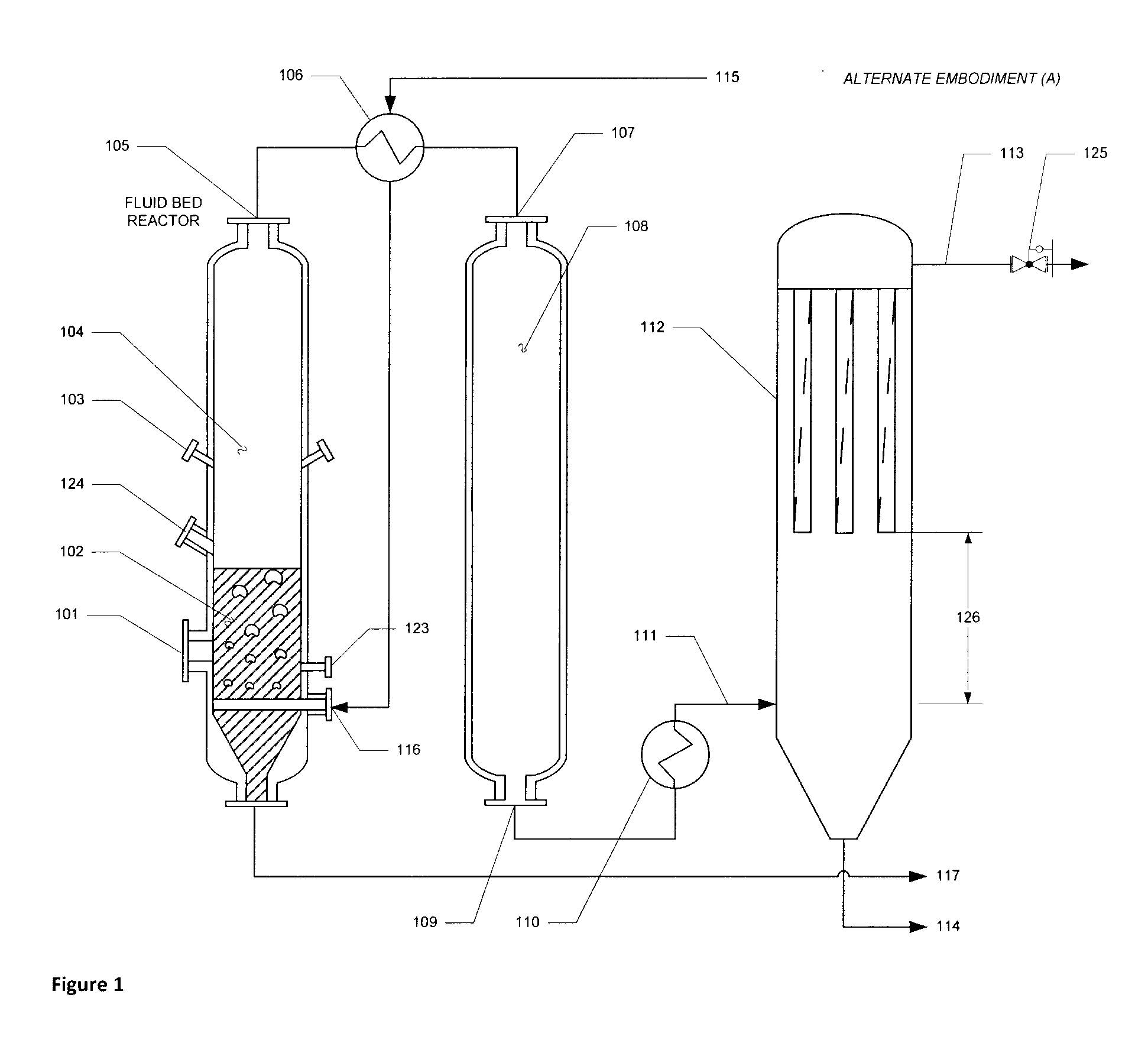
[0042]Table 1 provides the pertinent data providing a baseline against which the other examples will be compared. The baseline assumes that a singular sorbent effect is employed. In practice, multiple effects are at play. A bubbling fluid bed gasifier is operated at 1500° F. by feeding an appropriate ratio of air and fuel. Biomass is fed at the rate of 6500 lbs / hr and contains 251.4 ppm chlorine (dry basis). Granular limestone is co-fed at the rate of 1% of the biomass feed, or about 14.5 moles Ca / mol HCl. Gas is generated at the rate of 15,470 lbs / hr wet (2.38 lbs wet gas / lb biomass as fed). The initial HCl concentration is 100.0 ppmv in the freeboard, assuming 100% chlorine release as hydrogen chloride, and assuming there is no uptake of chloride by the biochar ash—even though it is known that biochar ash elements previously described have effective sorbent properties. The desired superficial velocity is 4 ft / second (a target for producing the desired lime and bio-char particle si...

example-2

[0043]This next example demonstrates the benefit of the gas-sorption residence time chamber or zone. The diameter of the gas-sorbent contact vessel (108) is modified from 2 ft to 8 ft, and the length retained at 30 ft.

[0044]The optimized temperature set point result is presented in Table 2. Trend study for this example is presented in FIG. 7. The optimized case achieves 3.3 ppm HCl (˜96.7% removal) with 825° F. in the filter vessel (112) and 900° F. in the intermediate gas-sorbent contact vessel (108). The final concentration is about 33% higher if the temperatures are equivalent in (108) and (112).

TABLE 2(Example 2) 100 ppmv HCl initial; 3.31 ppm HCl final, 20% moisture gas, 2.068 atm (15 psig); 15,470 pph gas.DwellKINETIC RESULTSLengthVolumeVelocityTime[HCl]EQ[HCl]% Cum.ZoneT (° F.)D (ft)(ft)(ft3)† (ft / s)(s)(ppmv)‡(ppmv)Capture1041500° 6.0020.0565.54.005.001944.0100.00.0%108900°8.0030.01508.01.7017.662.95913.986.1%112825°10.520.01392.50.93217.260.6023.3196.7%† Superficial velocity...

example-3

[0045]This third example demonstrates the benefit of added volume in the filter vessel by increasing its height by 17-ft beyond 20 ft (the height typically be used in an apparatus set up as described). This filter height extension could be done as a convenient way to increase sorbent contact residence time in the practice of this invention with or without including the intermediate sorbent contact vessel. The dimensions of the gas-sorbent contact vessel (108) of Example-2 are retained in this third case, i.e., diameter modified to 8 feet, length the same at 30 feet.

TABLE 3(Example 3) 100 ppmv HCl initial, 1.00 ppm HCl final, 20% moisture gas, 2.068 atm (15 psig); 15,470 pph gas.DwellKINETIC RESULTSLengthVolumeVelocityTime[HCl]EQ[HCl]% Cum.ZoneT (° F.)D (ft)(ft)(ft3)† (ft / s)(s)(ppmv)‡(ppmv)Capture1041500° 6.0020.0565.54.005.001944.0100.00.0%108900°8.0030.01508.01.7017.662.95913.986.1%112825°10.537.02864.50.91436.200.3331.0099.0%† Superficial velocity.*Excludes volume of bags / filter e...


PUM

PropertyMeasurementUnit
velocityaaaaaaaaaa
constant velocityaaaaaaaaaa
contact residence timeaaaaaaaaaa

Abstract

An apparatus and method is presented for removing acid gases and other trace contaminants to very low levels in combustible gases generated from thermal gasification of biomass or refuse-derived fuels. The invention includes optimization of geometric variables, temperature and pressure set points via use of a pressurized bubbling fluidized bed reactor to convert granular raw (non-activated) sorbents and auto-generated biochar sorbents) into activated, highly dispersed, and ideally sized particles for removing acid gases and toxic metals. The system can incorporate a generated gas cooler, a gas-sorbent contact chamber or zone, and a novel filter (with or without additional gas cooling and residence time stages).

Description

[0001]This application claims the priority of provisional Application Ser. No. 61 / 395,682.BACKGROUND[0002]1. Field of Invention[0003]The present invention relates to processes and apparatus for removal of unwanted substances from thermally produced gases and, more specifically, to the removal of acid gases, hydrogen chloride and hydrogen sulfide gases, and toxic metal vapors such as mercury, and lead, from the same.[0004]2. Description of Prior Art[0005]Renewable opportunity fuels such as lignocellulosic biomass (“biomass”) and refuse derived fuels (“RDF”) from municipal or industrial waste are important feedstocks for future production of renewable power and synthetic fuels and chemicals. However, some of these fuels (especially rapid growing biomass and RDF) contains chlorine and other contaminants. Chlorine may exist in the ash as an inorganic salt, or may be bound to carbon (in organic form). The combustion or gasification of biomass (including RDF) will contribute to the releas...

Claims


Application Information

Patent Timeline
Patent Type & Authority Applications(United States)
IPC IPC(8): B01D53/12
CPCB01D53/12B01D53/83B01D2253/112B01D2255/2045B01D2255/2047B01D2257/2045B01D2257/60C10K1/008C10J3/482C10J3/84C10K1/003C10K1/024C10J2300/0916C10J2300/0956C10J2300/0983C10J2300/0996C10J2300/1884B01D2253/102Y02P20/145
Inventor REARDON, JOHN P.PASKACH, THOMAS J.EVANS, PAUL
Owner FRONTLINE BIOENERGY
Why Eureka
Try Eureka