

Modular fuel cell system
a fuel cell and module technology, applied in the field of fuel cell systems, can solve the problems achieve the effects of increasing the overall cost and complexity, narrow power generation range, and high efficiency
- Summary
- Abstract
- Description
- Claims
- Application Information
AI Technical Summary
Benefits of technology
Problems solved by technology
Method used
Image

Examples
first embodiment
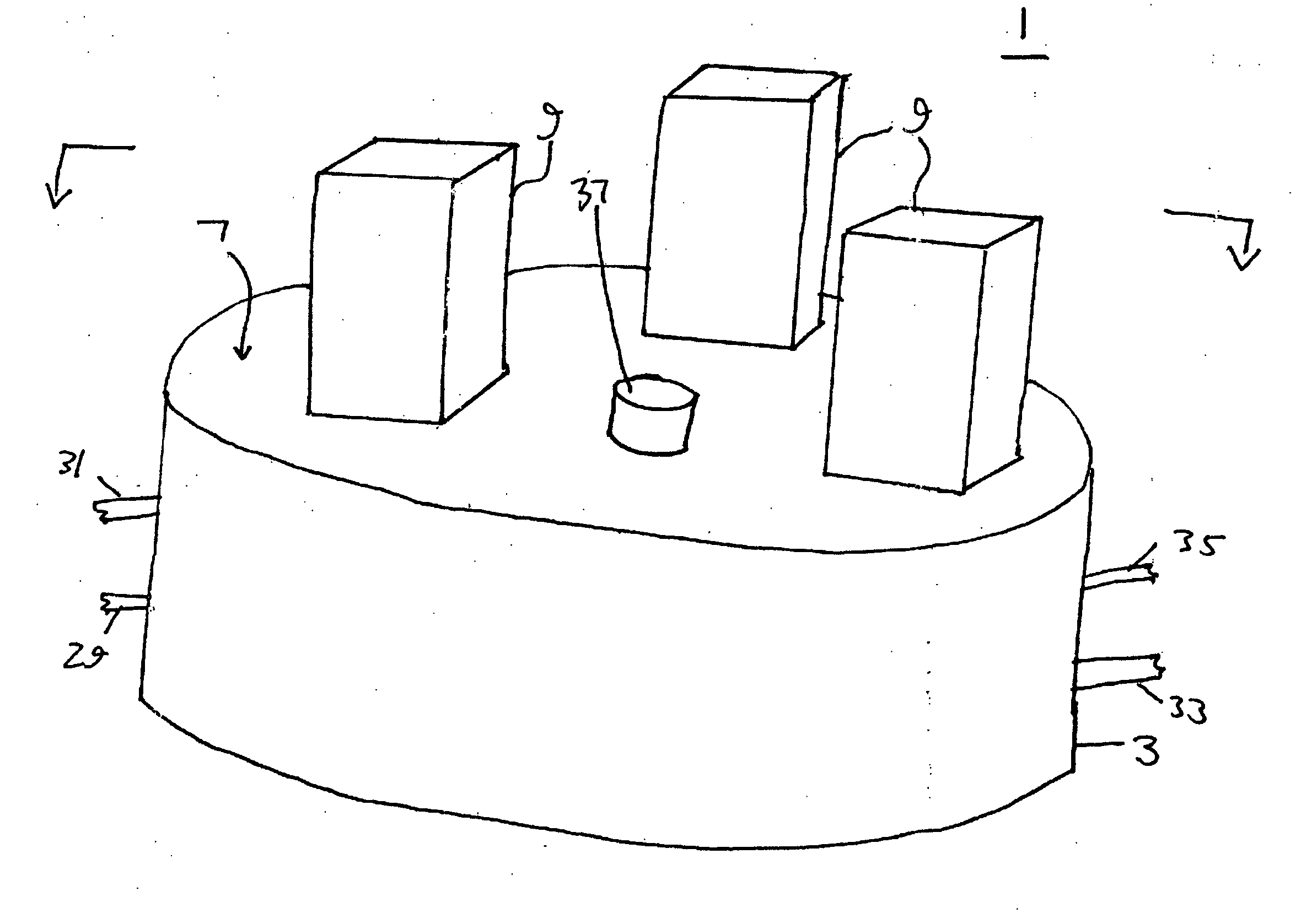
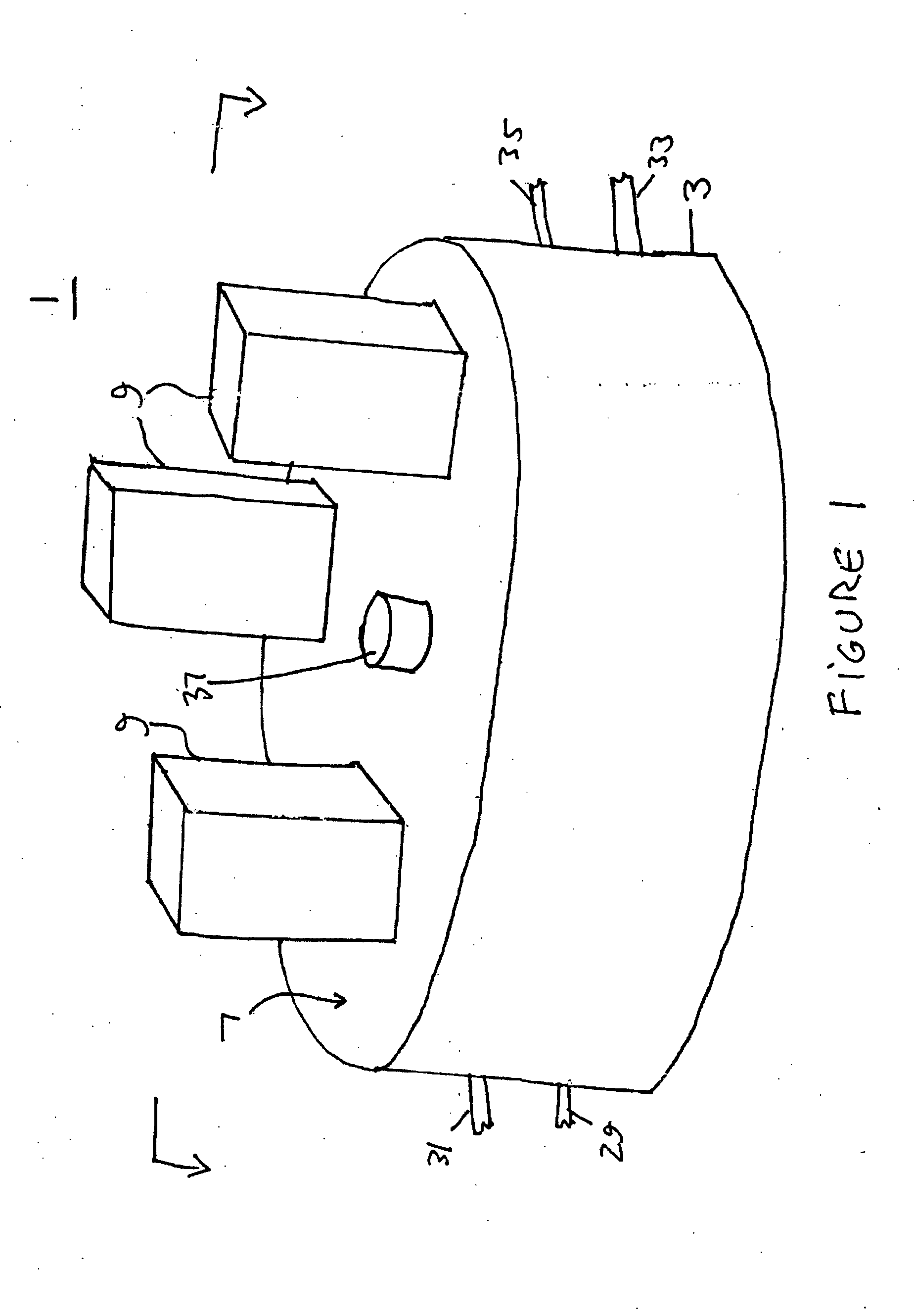
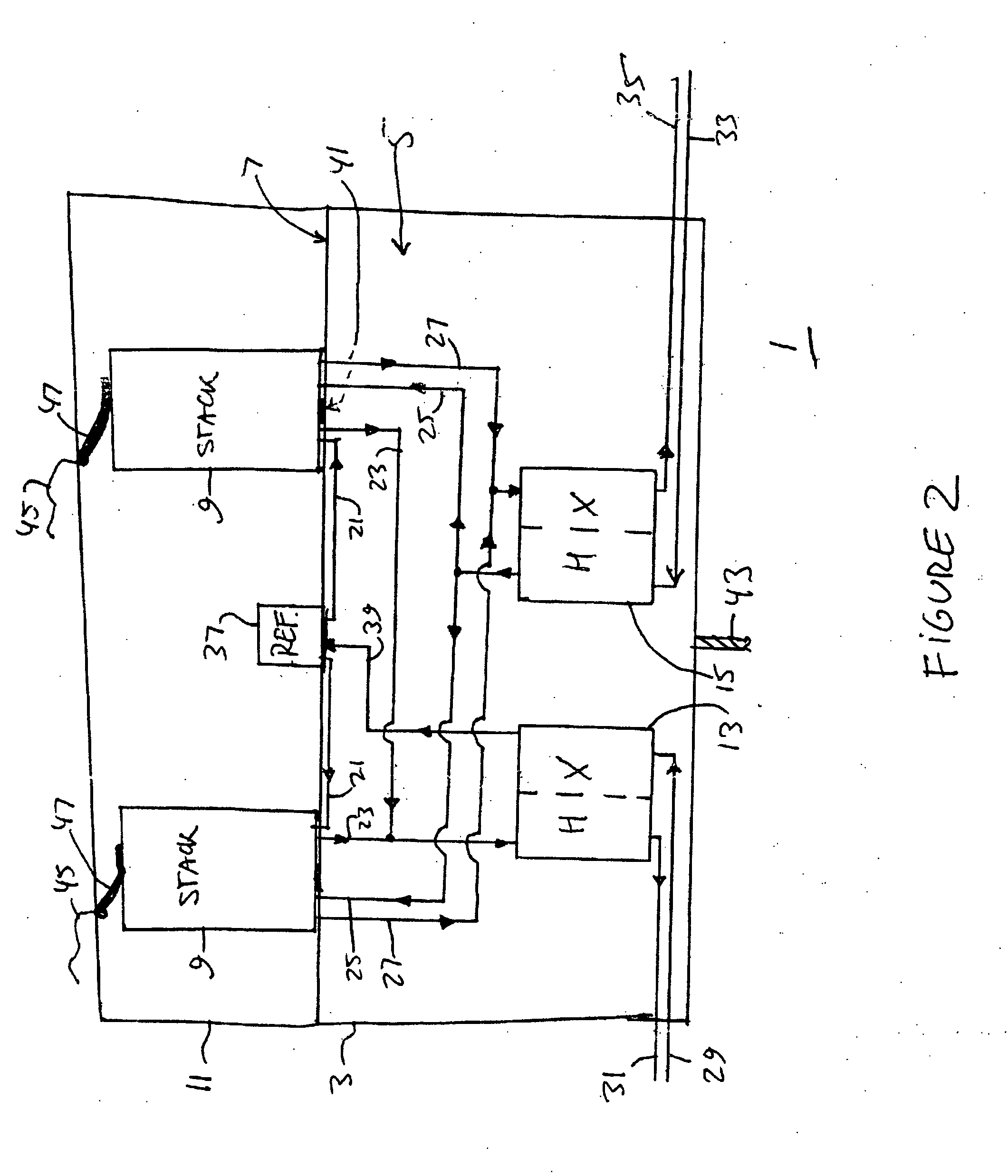
[0010]the invention provides a fuel cell stack module 1 which is illustrated in FIGS. 1, 2 and 3. The module 1 contains a base 3, which comprises a chamber having an interior volume 5 and an upper surface 7. The base 3 may have a cylindrical shape, with a flat upper surface and a circular cross section, as shown in FIG. 1. However, the base 3 may have any other suitable shape, such as a square, rectangular, polygonal, oval or irregular cross section.
[0011]Each fuel cell stack module 1 includes at least one fuel cell stack 9 and a cover dome 11 covering the stack(s) 9. For example, a single fuel cell stack 9 may be located under the dome 11. Alternatively, two or more stacks 9 may be located under the dome 11. The stacks 9 may be stacked vertically and / or horizontally under each dome 11. If desired, the vertically stacked fuel cell stacks 9 may be provided in a cascade configuration, where the fuel exhaust stream from one stack is used as the inlet fuel stream for an adjacent stack.
[...
second embodiment
[0030]the invention provides a modular design for the entire fuel cell system rather than just for the fuel cell stack modules. The modular system design provides flexible installation and operation. Modules allow scaling of installed generating capacity, reliable generation of power, flexibility of fuel processing, and flexibility of power output voltages and frequencies with a single design set. The modular design results in an “always on” unit with very high availability and reliability. This design also provides an easy means of scale up and meets specific requirements of customer's installations. The modular design also allows the use of available fuels and required voltages and frequencies which may vary by customer and / or by geographic region. Thus, in summary, since the fuel cell system is designed as a modular set, it can be installed to accommodate the requirements of different customers and the elements of the system are able to work in concert to achieve a very high syst...
third embodiment
[0049]In the system of the third embodiment, a portion of the fuel cell stack fuel exhaust stream is directly recycled into the fuel inlet stream. Another portion of the fuel cell stack fuel exhaust stream is provided into a partial pressure adsorption apparatus, and the separated hydrogen is then recycled into the fuel inlet stream and / or is provided to a hydrogen storage vessel or to a hydrogen using device.
[0050]FIG. 6 illustrates a fuel cell system 100 of the third embodiment. The system 100 contains a fuel cell stack 101, such as a solid oxide fuel cell stack (illustrated schematically to show one solid oxide fuel cell of the stack containing a ceramic electrolyte, such as yttria stabilized zirconia (YSZ) or scandia stabilized zirconia (SSZ), an anode electrode, such as a nickel-YSZ or Ni—SSZ cermet, and a cathode electrode, such as lanthanum strontium manganite (LSM)). It should be noted that the stack 101 may correspond to one of the stacks 9 located in the fuel cell stack mo...
PUM
| Property | Measurement | Unit |
|---|---|---|
| Pressure | aaaaa | aaaaa |
| Polarity | aaaaa | aaaaa |
| Volume | aaaaa | aaaaa |
Abstract
Description
Claims
Application Information