
Multiply-conductive Matrix for Battery Current Collectors

a current collector and multi-conductive technology, applied in the field of current collectors/electrodes for batteries, can solve the problems of reducing the energy density of the battery, and negate any weight savings achievable, so as to improve the energy density and power density, reduce the weight of the battery, and improve the structural integrity

Active Publication Date: 2011-11-24
JUNG JOEY CHUNG YEN
View PDF14 Cites 23 Cited by
  • Summary
  • Abstract
  • Description
  • Claims
  • Application Information

AI Technical Summary

Benefits of technology

[0012]Thus, there is provided an MCM that can be used to form a base for a current collector, and, hence, for electrodes, both anodes and cathodes. The MCM is composed of an ultra light substrate such as reticulated polyurethane foam (RPUF) that is treated with a conductive material so as to become electrically conductive. The conductive matrix, or current collector, is then optionally coated with a layer of metal or metal alloy for bonding to electro-active paste. The RPUF matrix has the advantage of having a higher specific surface area but is lighter than those of conventional current collectors, including current collectors using a carbon foam matrix.
[0014]The specific surface area of the different regions of the MCM determines the electrical conductance of the regions of the matrix once an electrical conducting material is applied to the matrix. I have discovered that by judicious choice and preparation of the polymer matrix substance, as disclosed below, if the frame region of a matrix has a high specific surface area relative to the body, the current-conducting properties will be enhanced and at the same time the frame will be denser and stiffer than the body. Consequently, such a frame enhances electrical current distribution through the electrode and simultaneously provides structural support for the electrode. This allows one to dispense with traditional lead frames. These advantages can be multiplied if the frame includes one or more strips that run through the body, as disclosed below.
[0020]The advantages of an MCM-based electrode according to the invention are many, but they are particularly evident in terms of power density relative to, for instance, carbon foam electrodes. For a lead-based battery, the invention results in reduced battery weight, improved structural integrity, and increased energy density and power density. Whereas performance of existing carbon foam electrodes lags behind the conventional lead electrodes, the MCM-based electrodes of the present invention offer substantially enhanced performance over both carbon foam and lead electrodes.

Problems solved by technology

These lead frames and / or lugs are relatively heavy, which negates any weight savings achievable from the use of carbon foam, and, consequently, there is basically no or negative gain in power density and little improvement in energy density.
An additional drawback is that carbon foam is fragile and lacks structural integrity, which complicates manufacturing processes such as battery pasting and battery assembling.
For example, metal-foil current collectors presently used in lithium ion batteries have at least two problems: 1) low volume cathode material loading, given that the battery has a very thin layer of cathode material applied onto the metal sheet current collector, limiting the battery capacity; and 2) high risk of thermal runaway due to poor electrical conductivity of the cathode material such as Li—CoO2, Li—MnO2, and Li—FePO4.
Thermal runaway may occur, for example, when a microscopic impurity such as copper or nickel is mixed inside the cathode material, which can converge on one spot, leading to a substantial electrical short and development of a sizable current between the positive and negative plates.

Method used


Image

  • Multiply-conductive Matrix for Battery Current Collectors
  • Multiply-conductive Matrix for Battery Current Collectors
  • Multiply-conductive Matrix for Battery Current Collectors

Examples


Embodiment Construction

Structure

[0032]References to elements, steps, features, and advantages herein with respect to a particular embodiment do not imply that those elements, steps, features and advantages apply to only that embodiment, or that they apply to all embodiments. Rather, such language is understood to mean that a specific element, step, feature, or advantage described in connection with an embodiment is included in at least that one embodiment. For the sake of clarity, structures, materials, or operations well-known in the art are not shown or described in detail in order to avoid obscuring the many novel aspects of the invention.

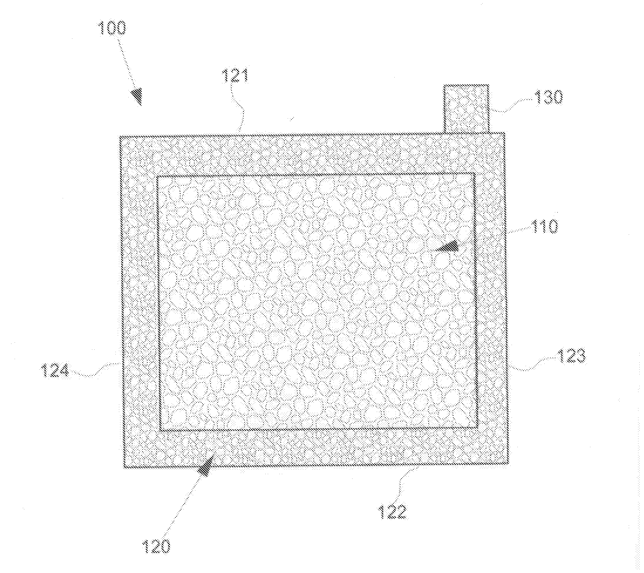
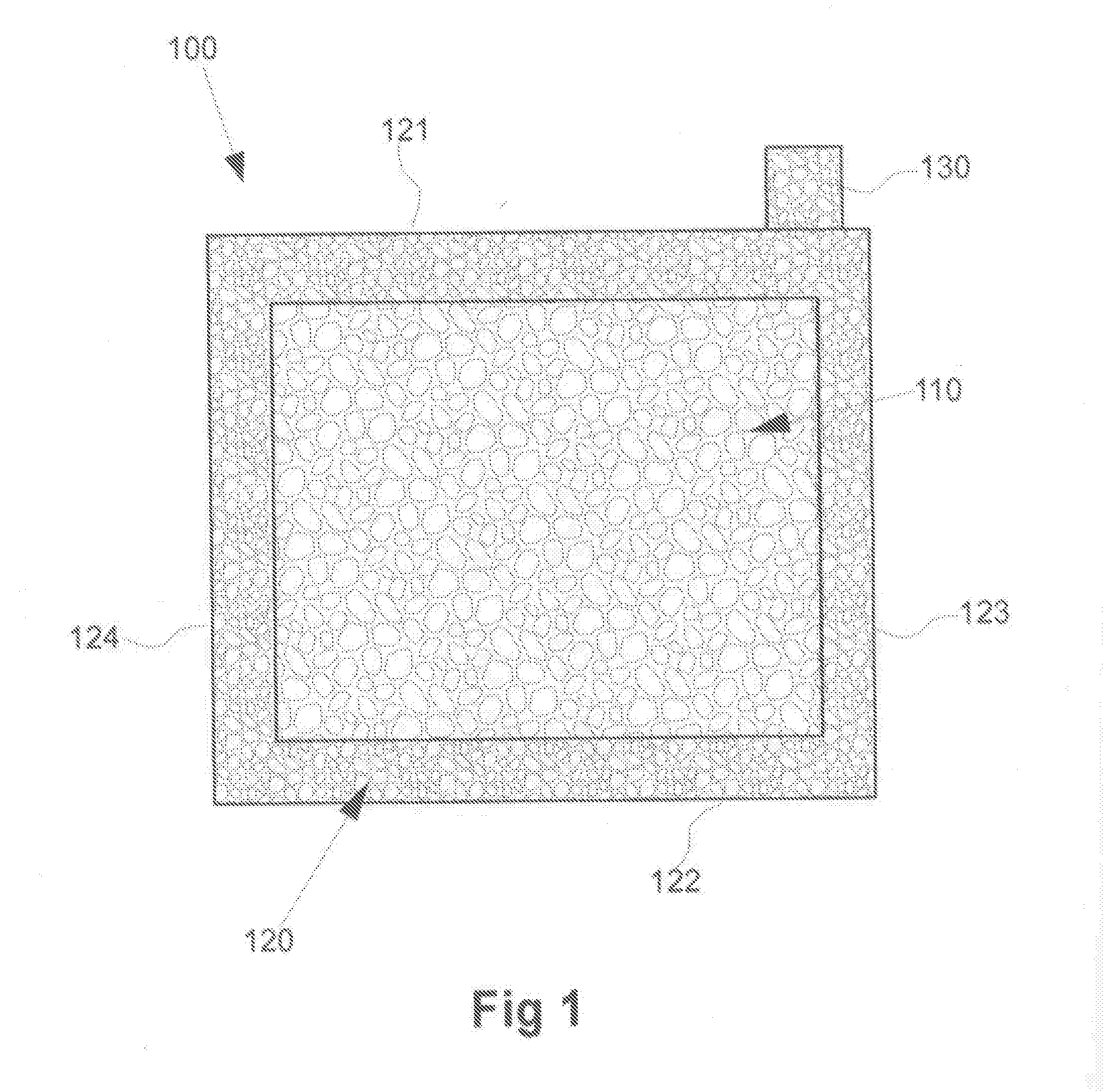
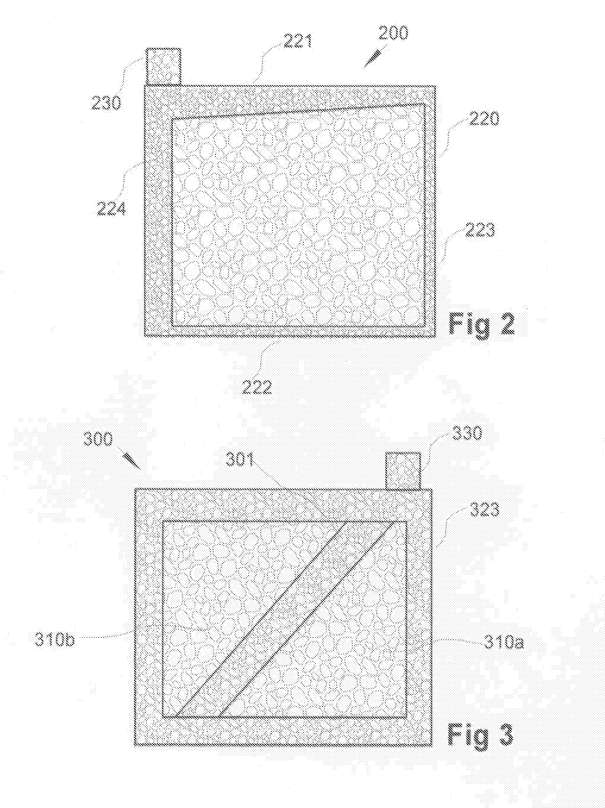
[0033]FIG. 1 is an illustration of a single-compartment embodiment of an MCM 100 in accordance with the present invention. The matrix has two distinct regions as indicated by the different fill patterns: body 110, and frame 120. The frame and body are made from two pieces of matrix substrate such as RPUF cut to shape and joined together as disclosed in the “Methods” s...


PUM

PropertyMeasurementUnit
thicknessaaaaaaaaaa
thicknessaaaaaaaaaa
height×width×thicknessaaaaaaaaaa

Abstract

A multiply-conductive matrix (MCM) for a current collector / electrode and a method of making the MCM are disclosed. The MCM includes a frame, preferably including a lug, the frame preferably made from a reticulated polymer foam substrate, and a body preferably made from the same substrate. The specific surface area of the frame is greater than the specific surface area of the body, resulting in greater rigidity and strength of the frame when the body and frame are joined to form an assembled matrix. Electrically conductive material is applied to the matrix to form the current collector. Optionally, a bonding material is also applied. Electro-active paste is applied to current if collector. The resulting MCM-based electrodes are ultra light and may be used as anode or cathodes in a lead-based battery, lithium ion battery, and nickel metal hydride battery for improved performance.

Description

STATEMENT OF PRIORITY[0001]Pursuant to 35 U.S.C. §371 I claim the priority benefits of international application PCT / CA2010 / 000006 filed on Jan. 5, 2010, which claims the priority benefits of U.S. Provisional Application 61 / 207,048 filed on Feb. 5, 2009.BACKGROUND OF THE INVENTION[0002]1. Field of the Invention[0003]This invention relates to current collectors / electrodes for batteries and methods for producing current collectors / electrodes.[0004]2. Description of the Related Art[0005]Since the very early days of commercially available lead-acid batteries in the late 19th Century, battery electrodes have been made from pasted plates. Such plates, called “current collectors,” commonly have a support base made of a porous matrix, such as a metal grid. Traditionally the grid is a lead alloy in which the holes are filled with an electro-active paste such as a mixture of red lead and 33% dilute sulfuric acid. The process of applying the paste to the matrix is referred to as “pasting”. The...

Claims


Application Information

Patent Timeline
Patent Type & Authority Applications(United States)
IPC IPC(8): H01M4/66H01M4/74H01M4/02
CPCH01M4/64H01M4/66Y10T29/10H01M4/668H01M4/808H01M4/663H01M4/667H01M4/82Y02E60/10Y02P70/50H01M50/531H01M50/50H01M4/72H01M4/745H01M4/742H01M4/747H01M4/74
Inventor JUNG, JOEY CHUNG YEN
Owner JUNG JOEY CHUNG YEN
Learn More