Scanner with feedback control

a scanner and feedback technology, applied in the direction of measuring devices, instruments, using optical means, etc., can solve the problems of non-uniform image intensity, inaccurate triangulation, and inability to properly identify beams

Inactive Publication Date: 2011-12-01
3SHAPE AS
View PDF4 Cites 63 Cited by
  • Summary
  • Abstract
  • Description
  • Claims
  • Application Information

AI Technical Summary

Benefits of technology

[0022]The present invention provides a scanning system and a method that can adjust the power of the laser beam such that the recorded intensity in the image can be maintained within the image sensor's dynamic range. The important aspects in this invention are that the fee

Problems solved by technology

A problem typically encountered with optical scanners is that the laser beam cannot be properly identified in the image, and thus the triangulation becomes inaccurate.
When the scanned object is not made of

Method used


Image

  • Scanner with feedback control
  • Scanner with feedback control
  • Scanner with feedback control

Examples


Embodiment Construction

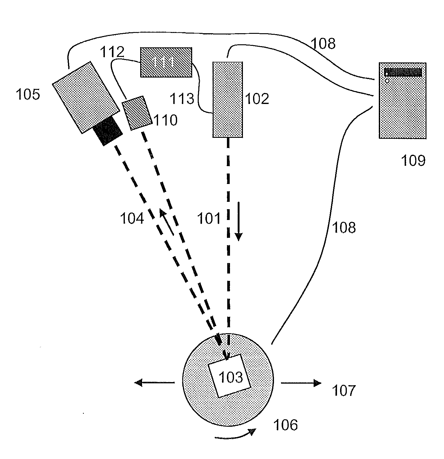
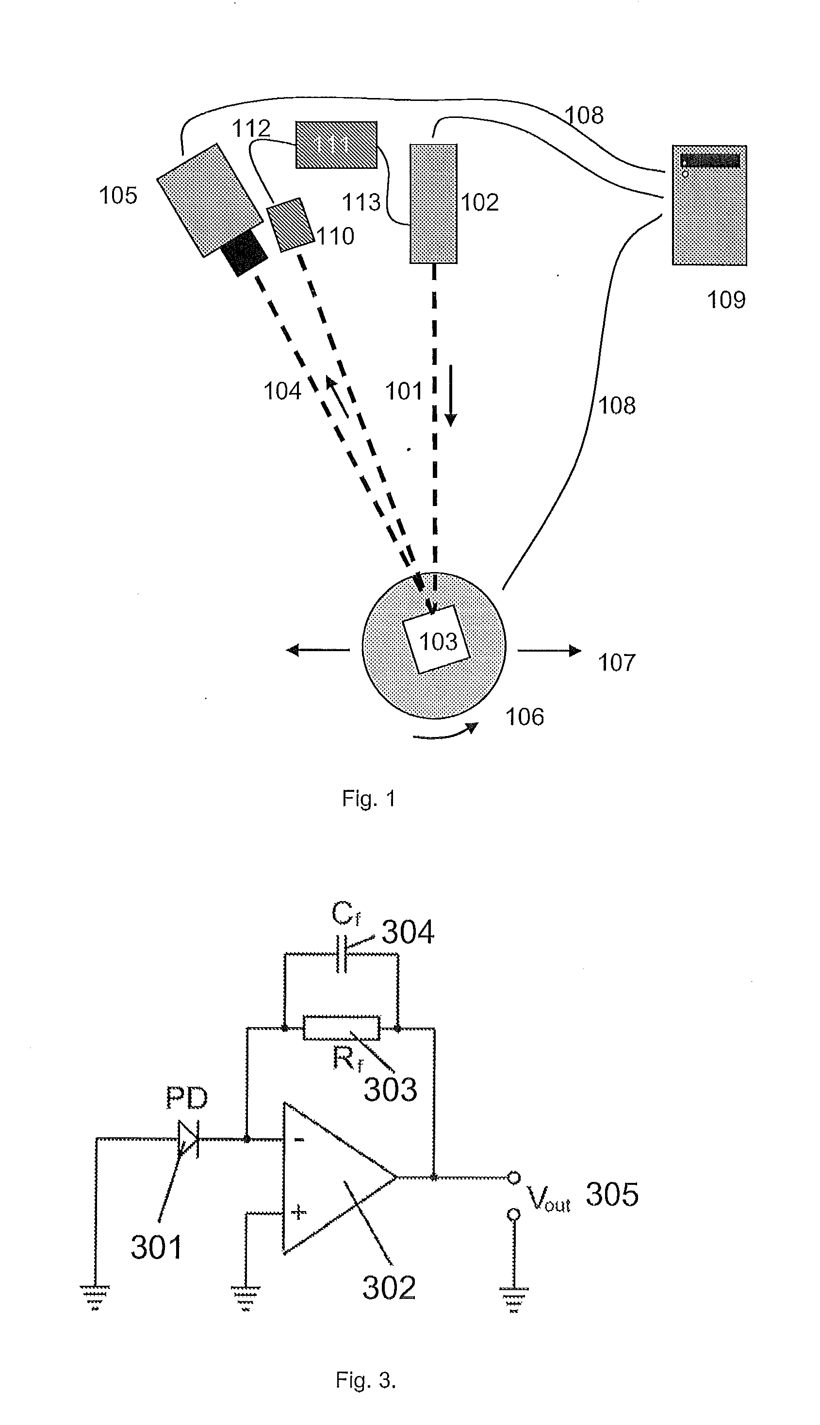
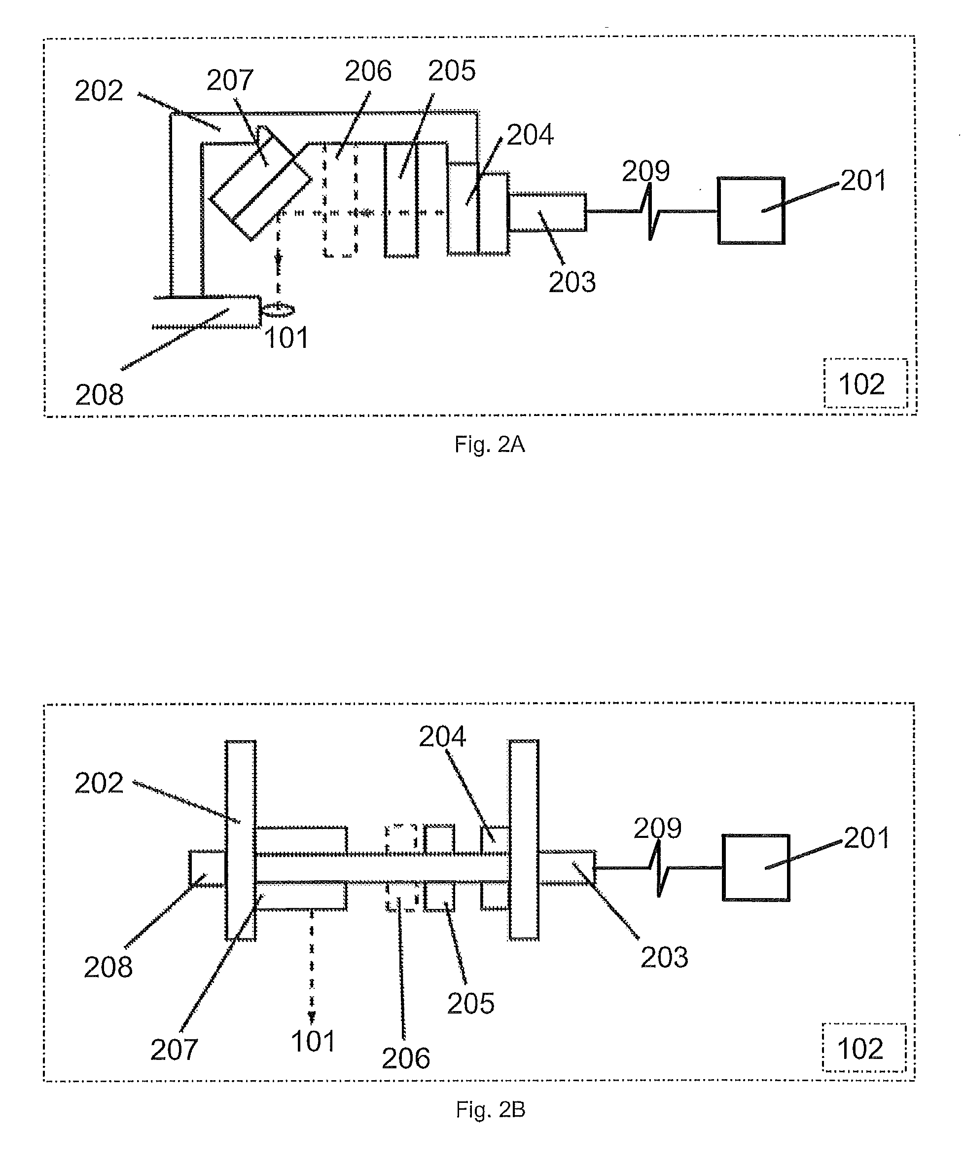
[0024]Unlike the optical scanning probe described in WO 2007 / 125081, this invention relies on a single element detector detecting scattered light from a single, continuously moving spot of light. Neither the generated line of light nor the detector(s) are pixellated, and this technique does not rely on spatial information from the camera or photodiode modules. The feedback control is wholly independent of information from the camera image. Neither is this invention necessarily “digital” in the sense the word is used on page 19 of WO 2007 / 125081. Either analogue signal processing electronics comprising discrete components can be used or else a digital version of the feedback control can be realised using a field-programmable gate array (FPGA), application specific integrated circuit (ASIC), a application specific standard product (ASSP) or a PC. A mixed signal circuit implementation would also be an embodiment of this invention.

[0025]One embodiment of the present invention overcomes ...


PUM


Abstract

The present invention relates to non-contact optical scanning of an object for generation of a three-dimensional surface model of the scanned object. In particular the invention relates to a scanner for obtaining the three-dimensional geometry of at least a part of the surface of an object, said scanner comprising: —at least one light source, preferably a laser light source with adjustable power, —projection means for directing light from the at least one light source to a moving spot on the surface of the object, —at least one image sensor adapted to record at least one image of at least a part of the surface, —detection means, other than the at least one image sensor, for monitoring at least a part of the light reflected from the surface, —regulation means for adjusting the intensity of the at least one light source based on the amount of light reflected from the surface, and—means for transforming the at least one image to a three-dimensional model of the surface.

Description

[0001]The present invention relates to non-contact optical scanning of an object for generation of a three-dimensional surface model of the scanned object.BACKGROUND OF THE INVENTION[0002]Laser scanners are widely used for many applications, both physically altering the scanned object (fine engraving, welding) or for detecting surface properties (bar code reading, digital three-dimensional surface reconstruction. The basic principle of a laser scanner is to direct a beam at the scanned object. By using optical elements such as lenses or mirrors, the beam can be directed in some spatial pattern, for example a line.[0003]A method for producing a digital three-dimensional model of a physical object is to direct a laser beam onto the surface of the object and record the image with a camera from a different angle. When the relative positions and the internal parameters of the beam generator and the camera are known, the three-dimensional shape of the illuminated part of the object can be...

Claims


Application Information

Patent Timeline
IPC IPC(8): G01B11/24
CPCG01B11/2518
Inventor HOLLENBECK, KARL-JOSEFOJELUND, HENRIKEDWARDS, CHRISTOPHER SIMONPLASCENCIA, ALFREDO CHAVEZFISKER, RUNE
Owner 3SHAPE AS
Why Eureka
Try Eureka