Multi-wafer rotating disc reactor with inertial planetary drive

a rotating disc and inertial planetary technology, applied in the field of vacuum processing systems and methods, can solve the problems of reducing the reliability and particle generation of cvd, degrading the process performance of cvd, and its own drawbacks, so as to minimize thermal expansion and thermal stress during operation, improve the uniformity of deposition, and optimize the mechanism's performance

Inactive Publication Date: 2011-12-08
VEECO INSTR
View PDF5 Cites 44 Cited by
  • Summary
  • Abstract
  • Description
  • Claims
  • Application Information

AI Technical Summary

Benefits of technology

[0012]Because the drive mechanism experiences an increased load over only a small portion of the operation period, the drive mechanism is not a source for particle generation during a typical operation cycle. In order to optimize the mechanism's performance in the high temperature environment of the reaction chamber, components such as gears, wafer platforms and the platen of the wafer carrier can be comprised of high-temperature resistant materials. In one embodiment, the bearings are comprised of a ceramic material, while the platen of the wafer carrier and the wafer platforms are comprised of SiC-coated graphite material to minimize thermal expansion, and thermal stresses during the operation.
[0013]The above embodiments present improvements over conventional methods of achieving a planetary motion, as well as improvement in deposition uniformity. The inertial drive mechanism, unlike the prior art mechanisms, creates the planetary motion in a controlled and synchronous manner for the wafer platforms. The planetary motion achieved by the mechanism does not experience a significant degradation in performance at the high rotation rates of the wafer carrier, nor significant mechanical degradation due to harsh operation environment, nor does the mechanism become a significant source for a particle generation or reaction gas contamination inside the reaction chamber. Such advancements in the mechanical performance of the mechanism produce corresponding improvements in the deposition uniformity by providing a more consistent and even exposure of substrates to the deposition source.

Problems solved by technology

Each of these systems has its own drawbacks.
Addition of the thermal stress due to high operational temperatures adds to the mechanical stress in the mechanism and results in lower reliability and higher particle generation.
Planetary motion through application of circulating gases limits operation of the wafers carrier to the low rpm range in order to maintain planetary motion as well as degrades CVD process performance by interfering with the reaction gases and increasing the total gas load on the system's pump.
The use of vibration to create planetary motion does not guarantee equal magnitude of rotation for all of the wafers on the wafer carrier as well as limits possible wafer carrier rotation rates.

Method used


Image

  • Multi-wafer rotating disc reactor with inertial planetary drive
  • Multi-wafer rotating disc reactor with inertial planetary drive
  • Multi-wafer rotating disc reactor with inertial planetary drive

Examples


Embodiment Construction

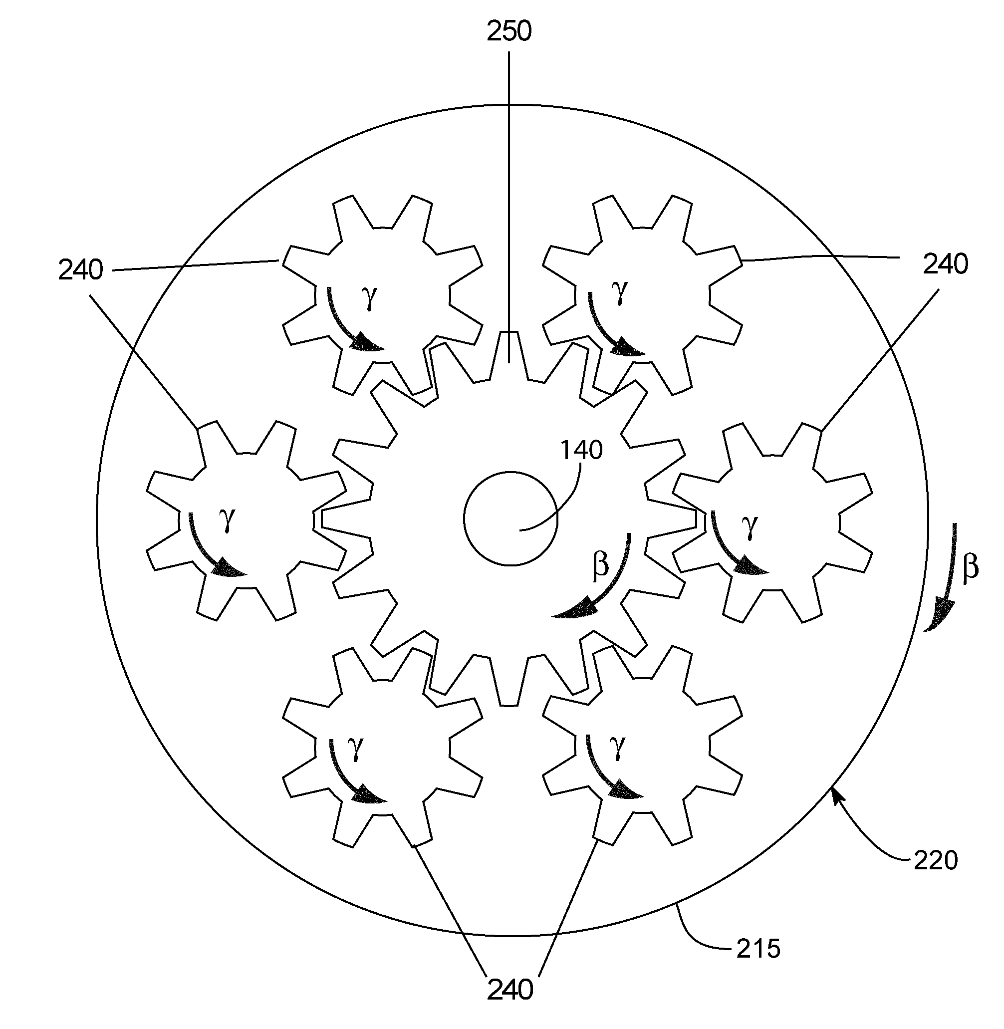
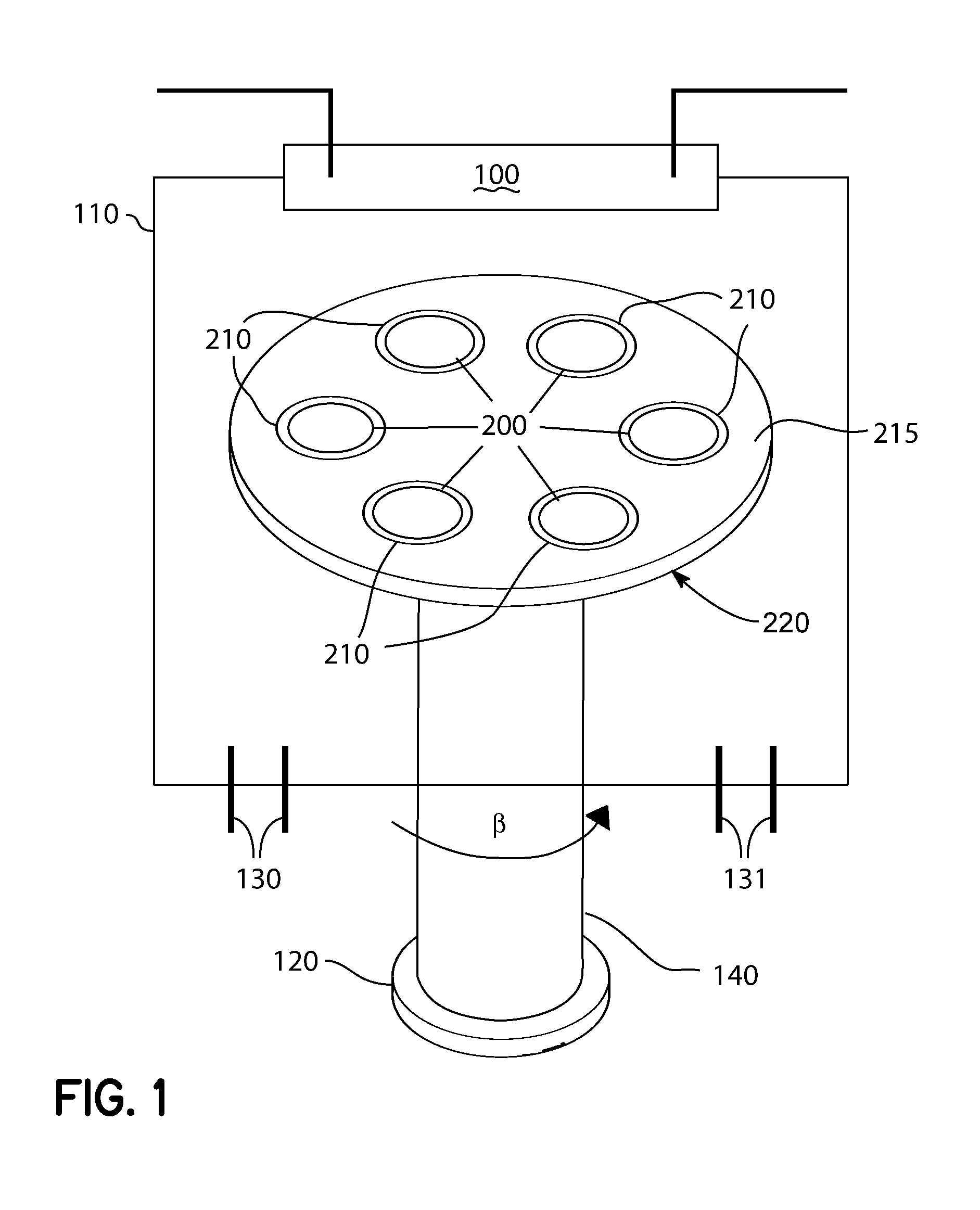
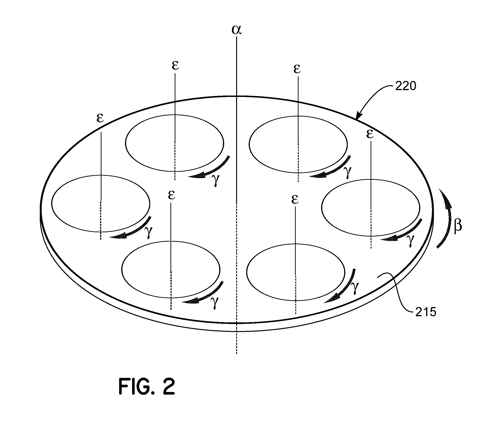
[0044]FIG. 1 provides a diagrammatic representation of an embodiment of a multi-wafer rotating disk reactor. A reaction chamber 110 includes a wafer carrier 220 and a flange 100 placed therein. The wafer carrier 220 includes a platen 215 and a plurality of wafer platforms 210 on which plurality of wafers 200 are placed. The wafer carrier 220 serves dual purposes of positioning the wafers 200 inside of the reaction chamber 110 as well support for the wafers 200 during wafer transfer in and out of the reaction chamber 110. The platen 215 of wafer carrier 220 is seated over the drive shaft 140, which is rotated by a motor 120.

[0045]The flange 100 may be a showerhead coupled with a precursor source configured to supply one or more precursor gases to the reaction chamber. In a typical MOCVD system, the precursor gases are composed of a metallorganic gas and the corresponding reacting species required for the chemical reaction. A plurality of substrates or wafers 200 are located inside of...


PUM

PropertyMeasurementUnit
angular velocitiesaaaaaaaaaa
rotationaaaaaaaaaa
diametersaaaaaaaaaa

Abstract

Wafer carriers and methods for moving wafers in a reactor. The wafer carrier may include a platen with a plurality of compartments and a plurality of wafer platforms. The platen is configured to rotate about a first axis. Each of the wafer platforms is associated with one of the compartments and is configured to rotate about a respective second axis relative to the respective compartment. The platen and the wafer platforms rotate with different angular velocities to create planetary motion therebetween. The method may include rotating a platen about a first axis of rotation. The method further includes rotating each of a plurality of wafer platforms carried on the platen and carrying the wafers about a respective second axis of rotation and with a different angular velocity than the platen to create planetary motion therebetween.

Description

CROSS-REFERENCE TO RELATED APPLICATIONS[0001]This application claims the benefit of U.S. Provisional Application No. 61 / 351,966, filed Jun. 7, 2010, the content of which is hereby incorporated by reference herein in its entirety for all purposes.BACKGROUND[0002]The invention generally relates to vacuum processing systems and methods and, in particular, to mechanisms and methods for improving material uniformity in the chemical vapor and physical vapor deposition systems.[0003]Due to the current growth in the LED and OLED markets, there is an ever increasing demand for efficient and high throughput manufacturing methods and systems. Current high throughput manufacturing systems use chemical vapor deposition (CVD) to deposit material on several substrate wafers simultaneously and thus to maximize their throughput. Yield per wafer is typically related to the uniformity of the deposition on it, with a more uniform deposition resulting in a higher yield.[0004]In the past and current CVD ...

Claims


Application Information

Patent Timeline
Patent Type & Authority Applications(United States)
IPC IPC(8): C23C16/458B05C13/02
CPCC23C16/4584H01L21/68771H01L21/68764C23C16/458H01L21/683H01L21/687
Inventor CELARU, ADRIANLUSE, TODD A.PARANJPE, AJIT P.SCANDARIATO, JOSEPHTANG, QUINFU
Owner VEECO INSTR
Why Eureka
Try Eureka