Waste tire recycling system

a waste tire and recycling technology, applied in the field of waste tire recycling system, can solve the problems of waste tire use as fuel, waste of resources, waste of resources, etc., and achieve the effect of stable and reliable system operation and enhanced convenience in initial operation

Inactive Publication Date: 2011-12-15
JEON YEONG MIN
View PDF4 Cites 8 Cited by
  • Summary
  • Abstract
  • Description
  • Claims
  • Application Information

AI Technical Summary

Benefits of technology

According to the system for recycling waste tires can enhance convenience in initial operation by providing with various carrier gases during initial operation thereof.
In the system which the condensed gas produced during the burning of waste tires is used as carrier gas, when the non-co

Problems solved by technology

The Ministry of Environment prohibits the usage of the waste tires as fuel since they produce various environment pollutions such as sulfur oxides, non-burned hydrocarbon, and sooty smoke when burned.
The waste tires are recycled as footpath blocks, recycled tires, recycled rubber, art fishing banks, and buffers of any structure, but their appliance is limited.
Also, scrapped materials and pollutions are produced when the recycled products are manufactured, and environmental pollution will be caused when they are scrapped.
The direct heating method has a risk for explosion since a flame produced when the waste tires are heated is chemically reacted with the oxygen contained in air in the furnace.
Also, the oil produced by the direct heating method contains moist and glass carbon, which causes the quality of the oil to be worse.
The indirect heating method has no risk for explosion different from the above the direct

Method used


Image

  • Waste tire recycling system
  • Waste tire recycling system
  • Waste tire recycling system

Examples


Embodiment Construction

The above and other objects and advantages of the present invention will become readily apparent by reference to the following detailed description.

Hereinafter, a system for recycling waste tires according to preferred embodiment of the present invention will be described in detail with reference to the accompanying drawings.

Note that the same components or parts are shown to have same reference numbers in the drawings. In describing the present invention, any related known function or structures are not described in detail so as to not vague the gist of the present invention.

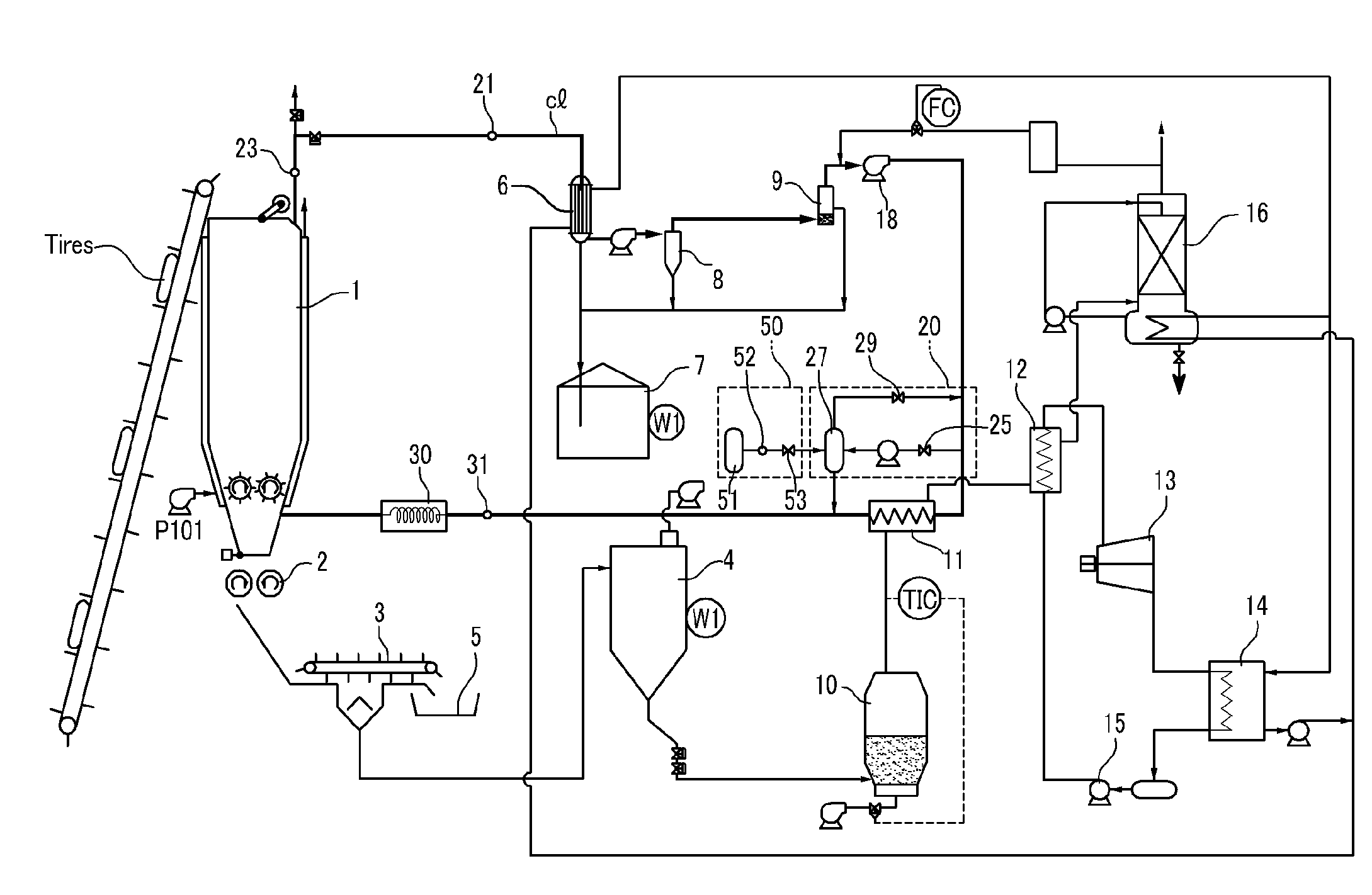
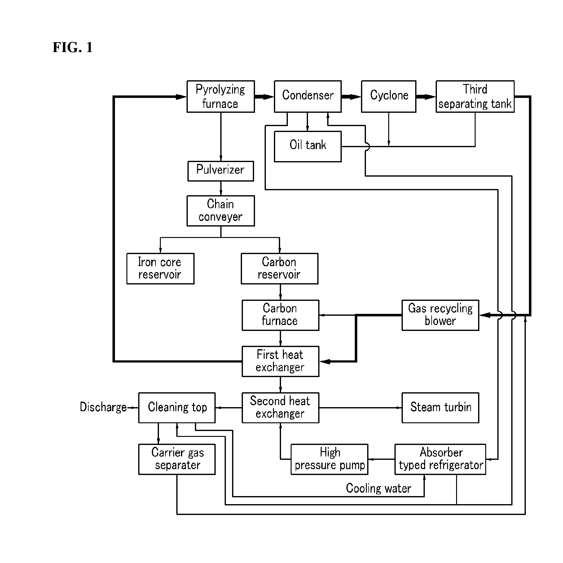
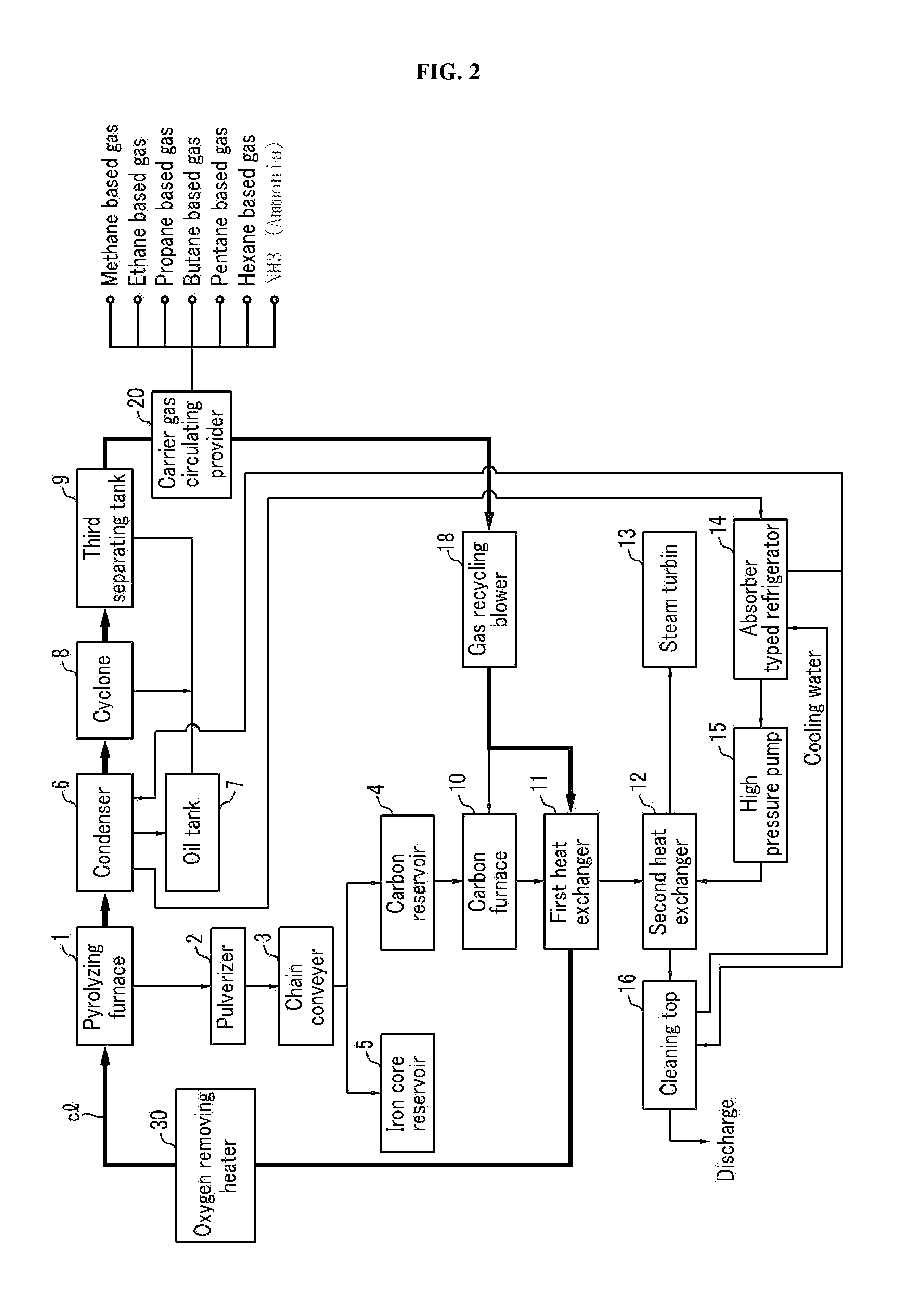
FIG. 2 is a block view schematically illustrating a structure of a system for recycling waste tires according to a preferred embodiment of the present invention.

Firstly, the main elements of the present invention are explained as follows.

Reference numeral (1) is a pyrolyzing furnace (1) for pyrolyzing waste tires by a direct heating method using gas such as carbon dioxide (CO2) or nitrogen (N2) as a carrier gas...


PUM

PropertyMeasurementUnit
Temperatureaaaaaaaaaa
Pressureaaaaaaaaaa

Abstract

Disclosed is a waste tire recycling system. More particularly, the present invention relates to a waste tire recycling system having a pyrolysis furnace in which waste tires injected are recycled with a carrier gas and decomposed by a direct heating method, an oil-collecting means for cooling and condensing hot steam generated from the pyrolysis furnace and collecting oil, and a carrier gas recycling line through which a carrier gas is recycled back into the pyrolysis furnace via the pyrolysis furnace and the oil collecting means, the waste tire recycling system comprising a carrier gas feeder connected to one end of the carrier gas recycling line to selectively feed a carrier gas by controlling a valve, the carrier gas feeder having a filling element filled with a carrier gas containing at least one of methane, ethane, propane, butane, pentane, hexane and ammonia group components in a mixed form.

Description

TECHNICAL FIELDThe present invention relates to a system for recycling waste tires enabling to extract various energy sources from the waste tires by pyrolyzing the waste tires through a heating method using carrier gas, and more particularly, to a system for recycling waste tires enabling to improve convenience in operation by providing carrier gas containing various gases from outside.BACKGROUND ARTRecently, the demand for tires is rapidly increasing according to the increasing of the demand for vehicles, and therefore the amount of the waste tires is also increased.As well known, the waste tires are mainly composited high polymer compounds, and their caloric value is about 34 MJ / kg which is higher than 29 MJ / kg of a standard caloric value. Further, the general composition of tires is 43.5 wt % of styrene-butadiene copolymer, 32.6 wt % of carbon black, 21.7 wt % of oil, and 2.2 wt % of additives such as sulfur and zinc oxide except for iron cores and nylon.The Ministry of Environm...

Claims


Application Information

Patent Timeline
IPC IPC(8): C10B49/02
CPCB29B17/04B29B2017/0496B29L2030/00C10G2300/1003C10B53/07C10G1/10C10B49/02Y02P20/143Y02W30/62B09B3/00B29B17/02
Inventor JEON, YEONG MIN
Owner JEON YEONG MIN
Why Eureka
Try Eureka