
BIOMASS BOILER SCR NOx AND CO REDUCTION SYSTEM

a biomass boiler and nox technology, applied in the direction of combustible gas purification/modification, lighting and heating apparatus, separation processes, etc., can solve the problems of scr system sensitive to contamination and plugging, scrs can exhibit inefficient nox reduction, and the capital and operating cost is significant, so as to achieve a wide range of temperature and temperature range, reduce capital and operating costs, and improve nox control efficiency

Inactive Publication Date: 2011-12-22
2E ENVIRONMENTAL
View PDF2 Cites 38 Cited by
  • Summary
  • Abstract
  • Description
  • Claims
  • Application Information

AI Technical Summary

Benefits of technology

[0005]Temperature, the amount of reducing agent, injection grid design, and catalyst activity are factors that determine the removal efficiency of an SCR. The use of a catalyst results in two primary advantages of the SCR process over the selective non-catalytic reduction (SNCR) process: higher NOx control efficiency and reactions within a lower and broader temperature range. However, the benefits are accompanied by a significant increase in capital and operating cost. SNCR is a method to reduce NOx emissions by injecting, for example, ammonia or urea into the firebox of the boiler to react with the nitrogen oxides formed in the combustion process. This results in elemental nitrogen (N2), carbon dioxide (CO2), and water (H2O).

Problems solved by technology

However, the benefits are accompanied by a significant increase in capital and operating cost.
SCR systems are sensitive to contamination and plugging (e.g., from contaminants in the untreated gas).
Without tuning, SCRs can exhibit inefficient NOx reduction along with excessive ammonia slip due to not utilizing the catalyst surface area effectively.

Method used


Image

  • BIOMASS BOILER SCR NOx AND CO REDUCTION SYSTEM
  • BIOMASS BOILER SCR NOx AND CO REDUCTION SYSTEM
  • BIOMASS BOILER SCR NOx AND CO REDUCTION SYSTEM

Examples


Embodiment Construction

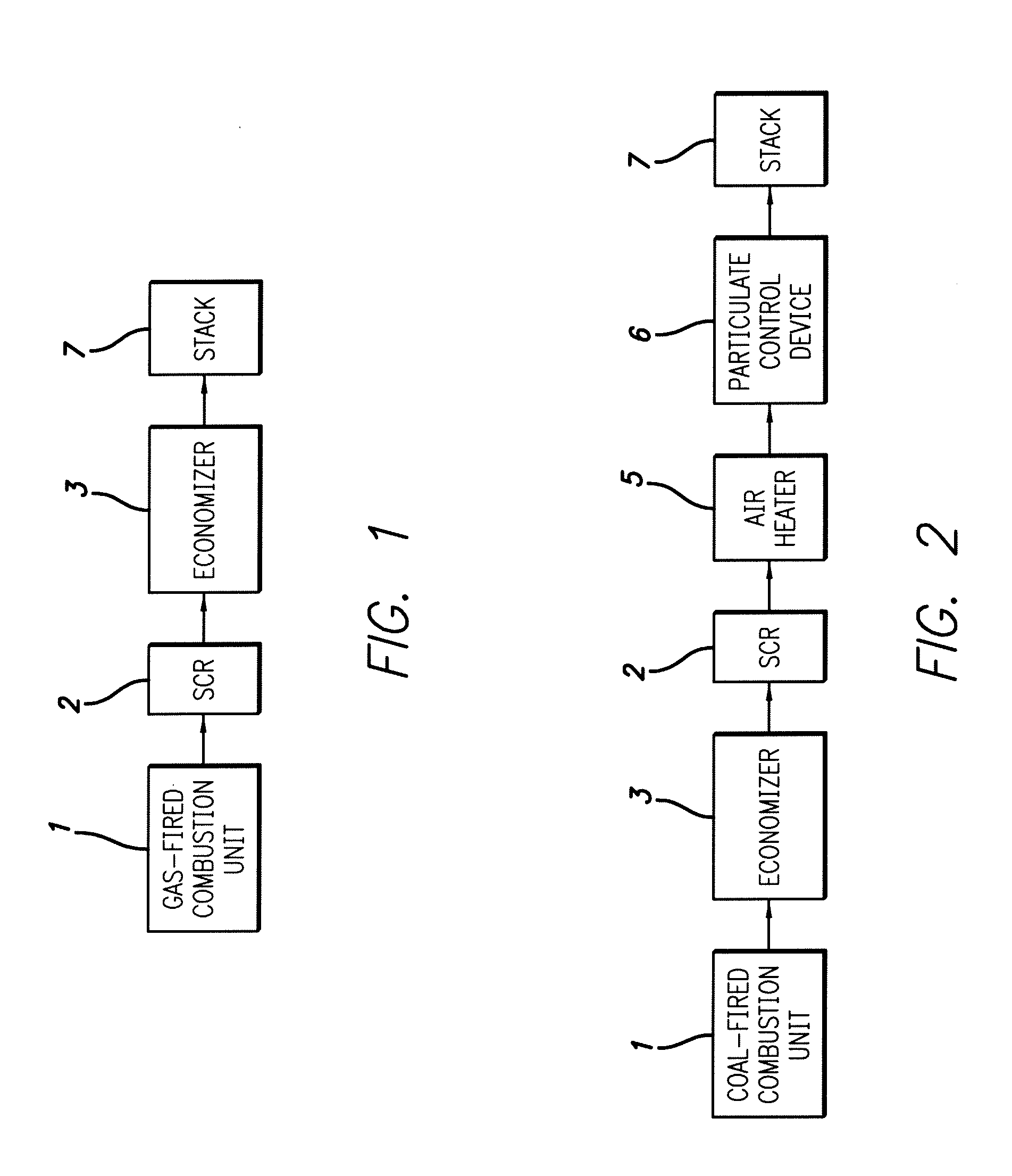
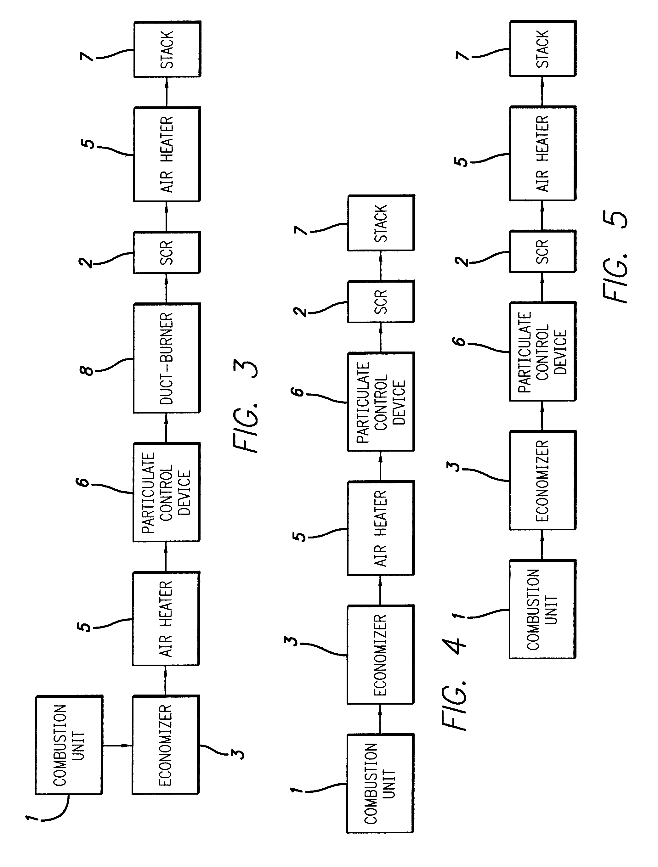
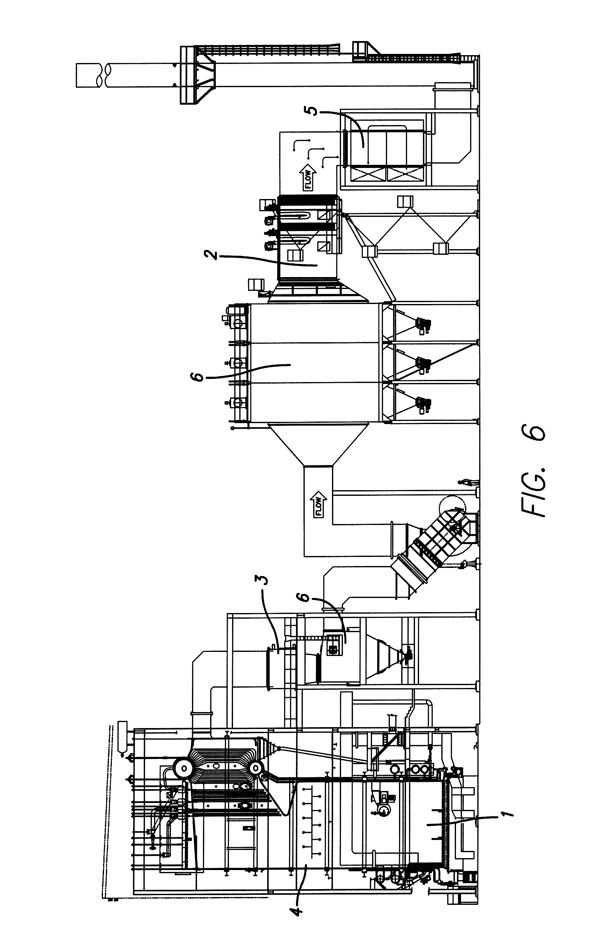
[0014]The present drawings demonstrate that there are several different locations downstream of the combustion unit 1 where SCR systems can be installed to effect the present invention. FIG. 1 shows a prior art gas-fired combustion unit 1 with an SCR located downstream. The remaining figures (Nos. 2-6) show different embodiments including the present invention. For example, an SCR is located downstream of the coal-fired combustion unit 1 and economizer 3, and upstream of the air heater 5 and particulate control device 6 (hot-side) as seen in FIG. 2. The flue gas in the locations shown in FIG. 1 and FIG. 2 is usually within the optimum temperature window for NOx and CO reduction reactions using metal oxide catalysts.

[0015]Solid biomass-fired combustion units 1 generate much more particulate matter (PM) than coal fired or liquid / gaseous fueled combustion units. PM creates fouling problems for SCRs, reducing catalyst life. In addition, the flue gas from biomass combustion units 1 conta...


PUM

PropertyMeasurementUnit
Temperatureaaaaaaaaaa

Abstract

A selective catalytic reduction system and method for reducing nitrogen oxide (NOx) emissions comprising a boiler producing flue gas emissions, a particulate control device receiving flue gas emissions from the boiler, a selective catalytic reduction unit (SCR) receiving flue gas emissions from the particulate control device and reducing nitrogen oxide (NOx) emissions, and a heat exchanger located downstream of the selective catalytic reduction unit (SCR) for removing heat from the flue gas for preheating at least one of boiler feed water and combustion air for the boiler.

Description

[0001]This application claims the benefit of the filing date of prior U.S. Provisional Application No. 61 / 357,235 filed Jun. 22, 2010, the subject matter of which is hereby incorporated by reference.BACKGROUND OF THE INVENTION[0002]Many steam turbine apparatus are known for generating power. Today's power plants need to meet the growing demand for electricity while achieving efficient combustion, low emissions, and no net CO2 releases into the environment. Biomass boilers equipped with new combustion techniques enhance efficiency, which, results in lower heat rates. Emissions control devices used with such boilers significantly reduce NOx and CO emissions so that higher energy demands can met.BRIEF SUMMARY OF THE INVENTION [0003]Selective Catalytic Reduction (SCR) (chemical reduction via a reducing agent and a catalyst) is utilized in large stationary fossil fuel combustion units such as electrical utility boilers, industrial boilers, process heaters, gas turbines, and reciprocating...

Claims


Application Information

Patent Timeline
IPC IPC(8): B01D53/56B01D53/62
CPCB01D53/56B01D53/8631B01D2251/2062Y10S423/06F23J15/025F23J15/04F23J2219/10B01D2251/2067
Inventor ELLERY, ROBERT
Owner 2E ENVIRONMENTAL
Learn More