Electrical system using high frequency ac and having inductively connected loads, and related power supplies and luminaires
a high frequency ac and inductive connection technology, applied in the direction of inductance, electroluminescent light sources, electric lighting sources, etc., can solve the problems of not working well with standard switch-mode power supplies, and achieve the effect of maximizing the efficiency and cost-effectiveness of compact leds and moderate illumination
- Summary
- Abstract
- Description
- Claims
- Application Information
AI Technical Summary
Benefits of technology
Problems solved by technology
Method used
Image
Examples
example 2
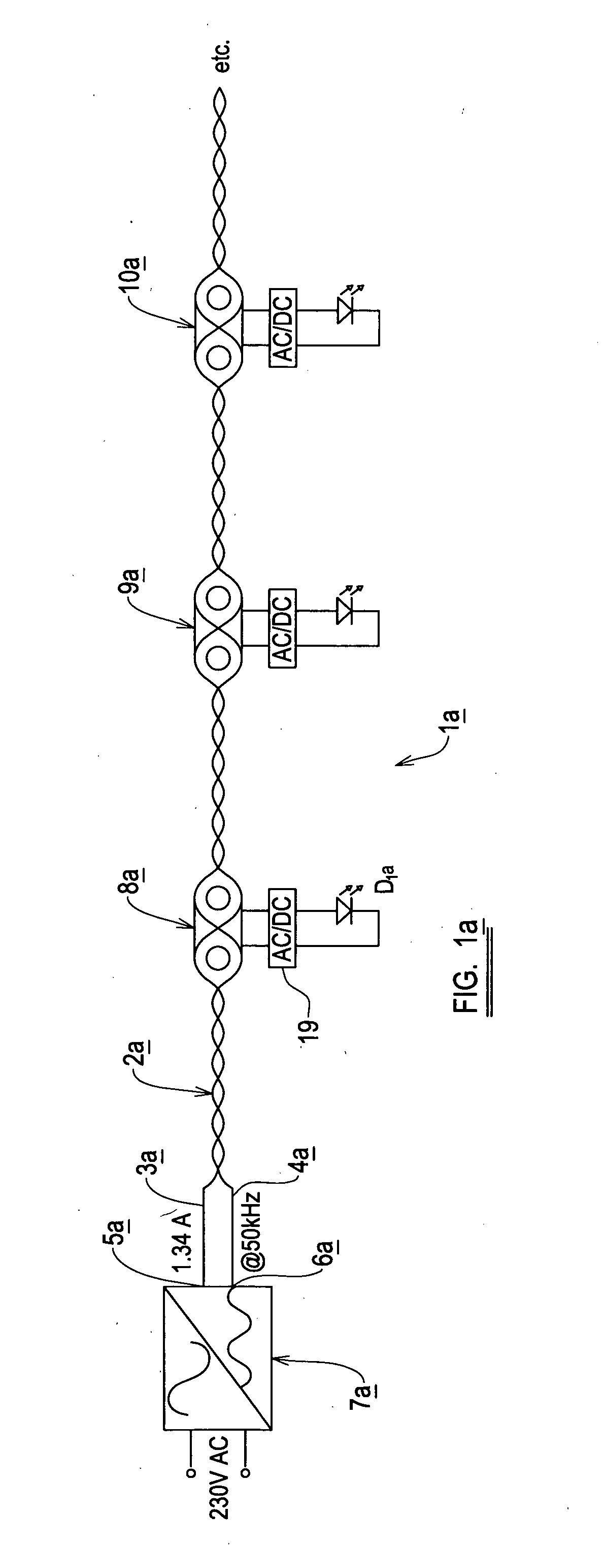
[0210]Referring now to FIGS. 4d and 5d of the accompanying drawings, a second embodiment of the invention again uses a PFC to provide a DC link voltage. This time it is fixed in value. The frequency of the inverter is varied to alter the current flow through the ballasting inductor. Because the current only varies in inversely proportional to the frequency, to obtain a useful range of control, a large range of frequencies would be needed to achieve the desired range. The effect can be enhanced by making the inductor resonant or partially resonant with a capacitor connected in parallel with the transformer primary. The resonant frequency is selected to be below or just below the lowest chosen operating frequency.
[0211]Selecting 50 kHz as the lowest frequency and a combination of ballasting inductor and resonant capacitor of 46 kHz, a control range of 100% down to 2% can be achieved in the range 50 to 80 kHz.
[0212]As before the input phase angle is used to define the output current by...
example 3
[0213]Referring now to FIGS. 6d, 7d, 9d and 10d of the accompanying drawings, in a third embodiment of the invention the PFC stage is omitted entirely and the DC link rail is unsmoothed and varies at twice the input power frequency between zero and maximum. The inverter drives a resonant arrangement like the above. If the inverter operates at or near the resonant frequency the input current to the inverter tends to remain constant as the input voltage varies. The resonant ballasting arrangement produces a current in the load that varies proportionally with the input voltage to it. (At resonance even the smallest of input voltages “rings up” to begin driving the (fixed voltage) load.) In consequence the power to the load is nominally sinusoidal, despite its threshold. As the input voltage is sinusoidal the input current must be constant as the ballasting arrangement is nominally lossless.
[0214]This is a very attractive state of affairs as, though the load is not unity power factor, i...
example 4
[0218]Referring now to FIGS. 6d, 8d, 9d and 10d of the accompanying drawings, example 4 is a modified version of example 3 described above in which the approximated input squarewave current of embodiment 3 can be further “squared off” to enhance the effect of a high initial current. This is done by altering the frequency of operation throughout the input frequency half cycle, as shown in FIG. 8d. Hence the unit is run near resonance when the input voltage waveform is low. As the input voltage increases the inverter frequency is increased also, counteracting somewhat the effect of the increased input voltage on load current. Turning to FIG. 8.1d, the current in the load become more nearly square (when looked at with respect to the input power frequency)—this gives a constant power draw. Further, the smoothing of the output DC current is easier, becoming as it does nominally constant with brief dips in the zero crossing region of the input power frequency.
[0219]The input current can n...
PUM
| Property | Measurement | Unit |
|---|---|---|
| frequency | aaaaa | aaaaa |
| frequency | aaaaa | aaaaa |
| frequency | aaaaa | aaaaa |
Abstract
Description
Claims
Application Information
 - R&D
- Intellectual Property
- Life Sciences
- Materials
- Tech Scout
- Unparalleled Data Quality
- Higher Quality Content
- 60% Fewer Hallucinations
Browse by: Latest US Patents, China's latest patents, Technical Efficacy Thesaurus, Application Domain, Technology Topic, Popular Technical Reports.
© 2025 PatSnap. All rights reserved.Legal|Privacy policy|Modern Slavery Act Transparency Statement|Sitemap|About US| Contact US: help@patsnap.com


