[0011]One preferred embodiment of the invention is a turbocharger that is self-cooled by a flow of
compressed air generated by the turbocharger compressor and delivered within the turbocharger to the bearing housing to cool the internal structure of the turbocharger, including the turbocharger bearings. This embodiment eliminates the need for cooling fluids from outside the turbocharger, their necessary
piping and conduits and associated parts and labor and possibilities of unreliable operation. Where it is desirable to do so, the flow of cooling air can be can be increased by the addition of a pressure
relief valve that opens at a predetermined
pressure level to limit the maximum speed of the turbocharger to an acceptable level and eliminate the need for an
exhaust gas waste gate.
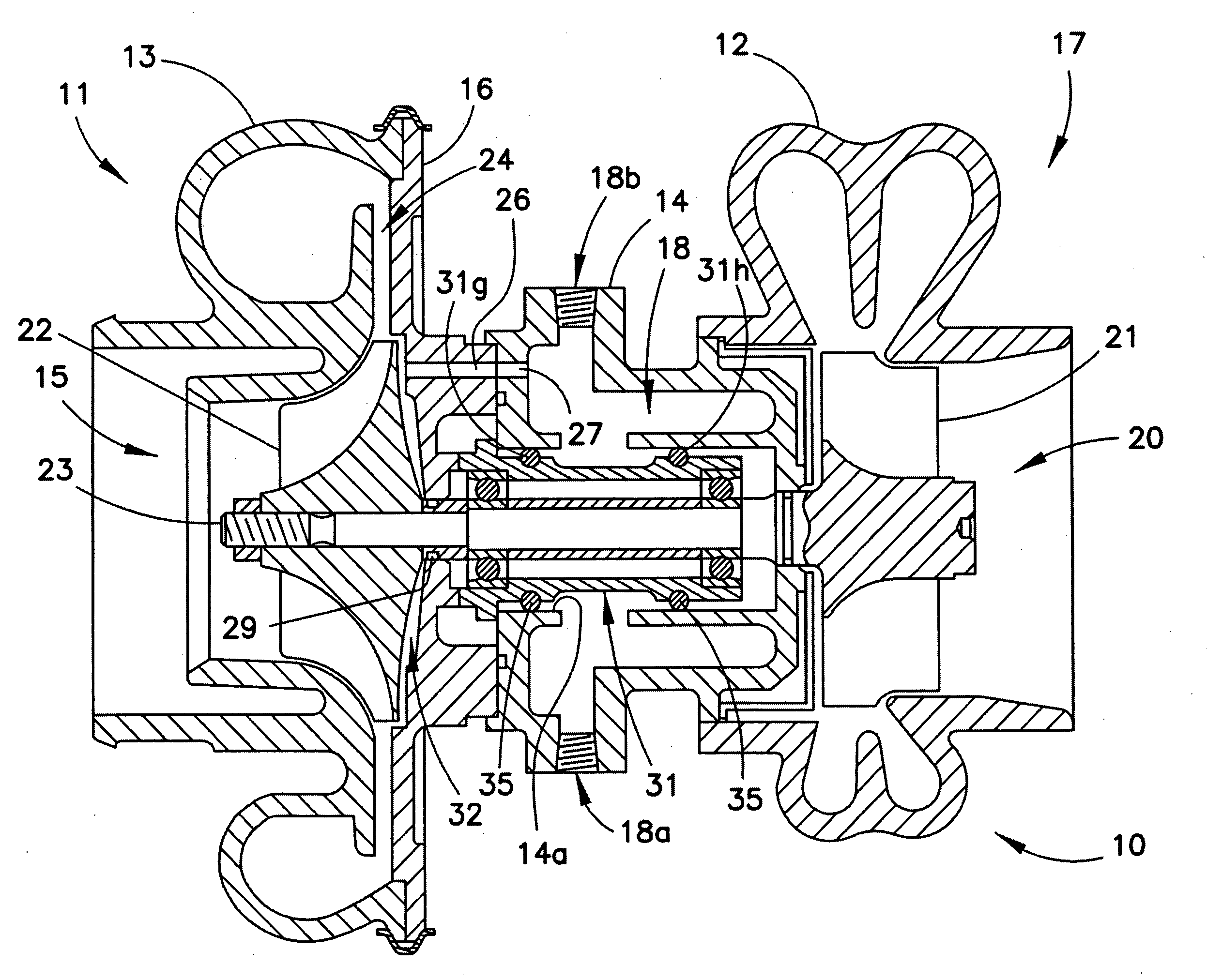
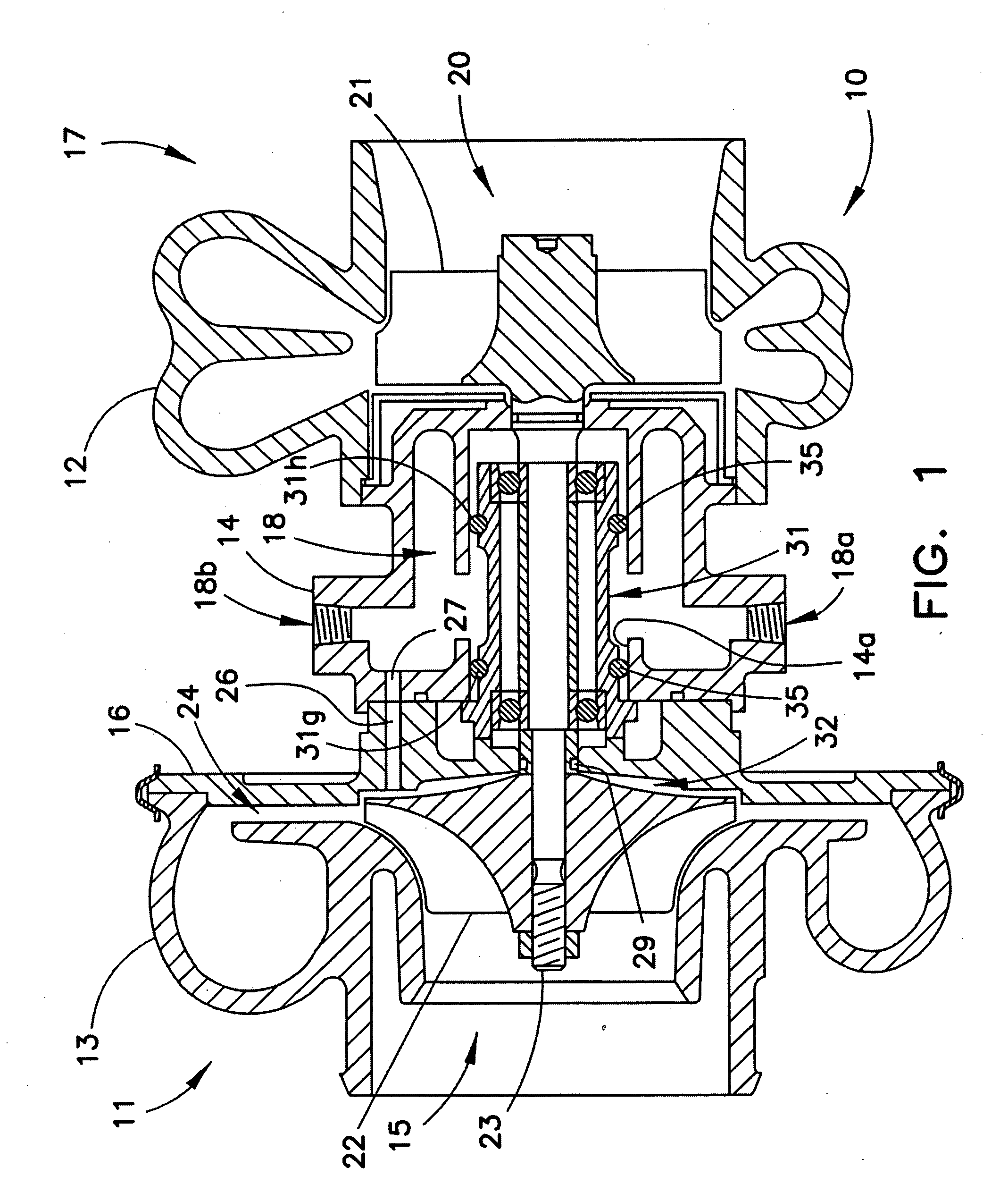
[0014]The invention can be accomplished by bleeding
compressed air from the area behind the compressor wheel into the cooling jacket in the bearing housing where it can cool the internal parts of the turbocharger, and then allow the heated air to vent to the
atmosphere. The air can be introduced into the bearing housing by means of simple drilled holes, leading from the area behind the compressor wheel into the cooling jacket. As the speed of the turbocharger increases, the pressure of the air behind the compressor wheel increases so that an increased flow of cooling air is bled into the bearing housing automatically to increase the air-
cooling effect as exhaust temperatures increase.
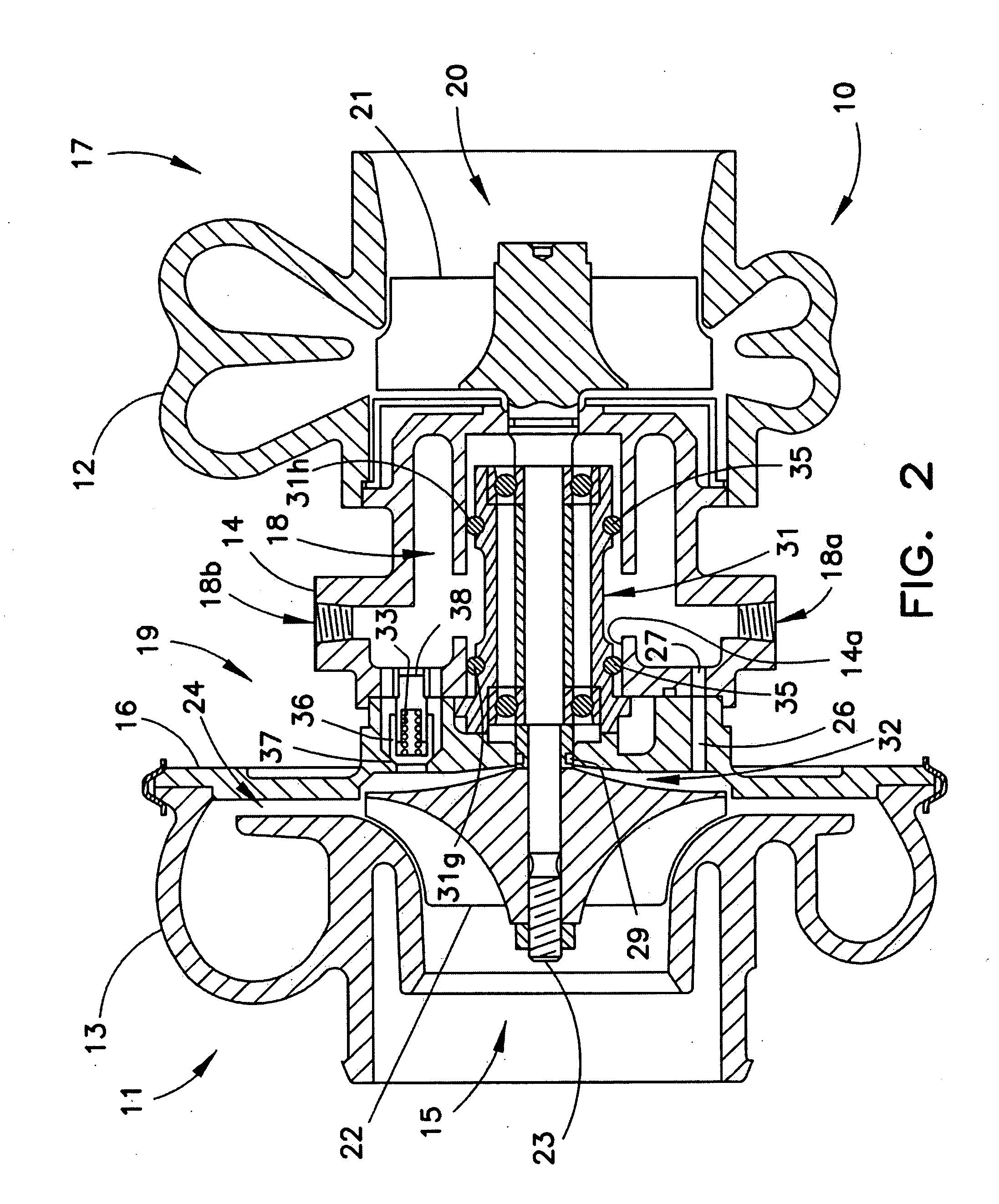
[0015]The invention can also eliminate the expensive waste gates and actuation mechanisms in the hot exhaust system and employ a simple pressure
relief valve in the cool part of the center section of the turbocharger to open when the compressor
discharge pressure reaches a predetermined value and admit an increased amount of cooling air into the bearing housing.
Compressed air is bled from the area behind the compressor wheel by small air passages (or drilled holes) that are always open or, as an alternative, can be combined with a larger pressure relief valve that communicates with the same area behind the compressor wheel. The pressure relief valve is fitted with a spring that holds the valve closed until a predetermined air charge pressure is reached. At this point, the
spring force holding the relief valve closed is overcome, allowing the valve to open to admit a much larger quantity of cooling air into the cooling jacket of the turbocharger bearing housing. This additional flow of
compressed air requires the
turbine of the turbocharger to produce more power, which it is capable of doing, over the high speed range of the engine. Thus, in this invention, the
excess energy in the
exhaust gas is not discarded through a waste gate, but is used to provide the larger quantity of cooling air when the relief valve behind the compressor wheel opens. The amount of additional cooling air provided through the relief valve will absorb
turbine power, and this absorption will increase as the engine speed reaches high values, thus preventing the
excess energy in the
exhaust gas from over-speeding the turbocharger.
[0016]The utilization of a
bleed air hole and pressure relief valve is a unique method of cooling the hot internal components of a turbocharger and, concurrently, preventing the turbocharger from exceeding its maximum
speed limit. This invention eliminates the conventional waste gates and the liquid cooling lines needed when engine
coolant is used to cool the internal components of the turbocharger.
Elimination of the waste gate and engine cooling lines results in a substantial cost saving since a simple spring-loaded relief valve is a reasonably inexpensive item.
[0017]If the air-cooled turbocharger of this invention also has a
grease-lubricated bearing system, as disclosed in U.S. Pat. No. 7,025,579 B2, then the lube oil lines to and from the turbocharger are eliminated. Thus, the air-cooled, oil-less turbocharger can be remotely mounted from the engine; for example, in the vicinity of a vehicle
muffler, thereby eliminating the long lube-oil lines and / or engine
coolant lines to the turbocharger and back from the turbocharger to the engine. This amounts to another substantial cost saving as a result of implementing this invention.
[0018]Additionally, the air bleed hole and relief valve combination of this invention can be easily designed into a turbocharger that has a bearing system using engine lubricating oil, as disclosed in U.S. Pat. No. 7,677,041 B2, if it has a cooling jacket in the bearing housing. It would be implemented in the same manner as illustrated in FIG. 1 and FIG. 2.

