
Method for Producing a Carbon Composite Material

a carbon composite material and composite material technology, applied in the direction of non-aqueous electrolyte accumulator electrodes, coatings, nanotechnology, etc., can solve the problems of limited application of lithium ion rechargeable batteries, safety issues, and inconvenient cathode materials such as licoosub>2 /sub>,

Inactive Publication Date: 2012-01-26
UNIVERSITY OF THE WESTERN CAPE
View PDF2 Cites 11 Cited by
  • Summary
  • Abstract
  • Description
  • Claims
  • Application Information

AI Technical Summary

Problems solved by technology

Recently it has been found that LiCoO2 is not suitable for application as cathode materials in large sized lithium ion rechargeable batteries, such as electric vehicles (EV) and hybrid electric vehicles (HEV).
In the large sized Li-ion battery, oxygen will release from LiCoO2 crystal when the operation temperature is over 50° C. and results in safety issues.
The extensive application of the lithium ion rechargeable battery is limited by the high cost of LiCoO2.
However the capacity drops rapidly, because its conductivity is very poor, so polarization is easily observed during the course of charge-discharge.
Unfortunately, the carbon formed on the surface of LiFePO4 particle is not uniform, which has a negative effect on the electrochemical performance of this composite cathode at high rate.
The synthesized LiFePO4 showed a very good electrochemical performance, however, this method is a relatively expensive process, and the cathode material prepared by this method is not suitable for cost conscious applications, such as EV and HEV, where large amounts of cathode materials are required.
But the electrochemical performance of this LiFePO4 / C composite is not very good at high rate due to non-uniform carbon coating formed on the surface of LiFePO4.
The capacity of resulting LiFePO4 / C composite is up to 90% theoretical capacity at 0.2 C. However, xerogels and aerogels have poor packing density, which will lead to low volumetric density of large-sized Li-ion secondary battery.

Method used


Image

  • Method for Producing a Carbon Composite Material
  • Method for Producing a Carbon Composite Material
  • Method for Producing a Carbon Composite Material

Examples


example 2

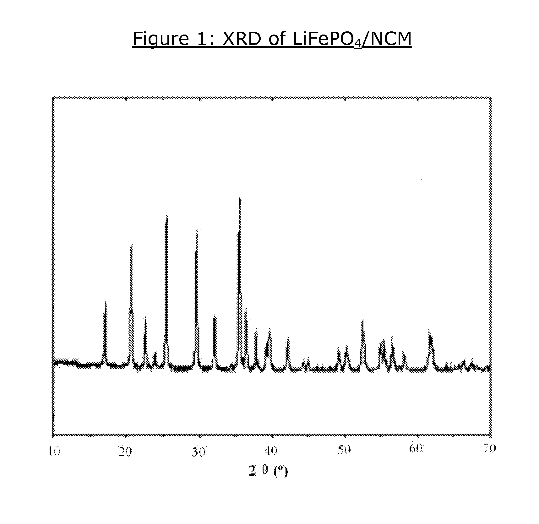
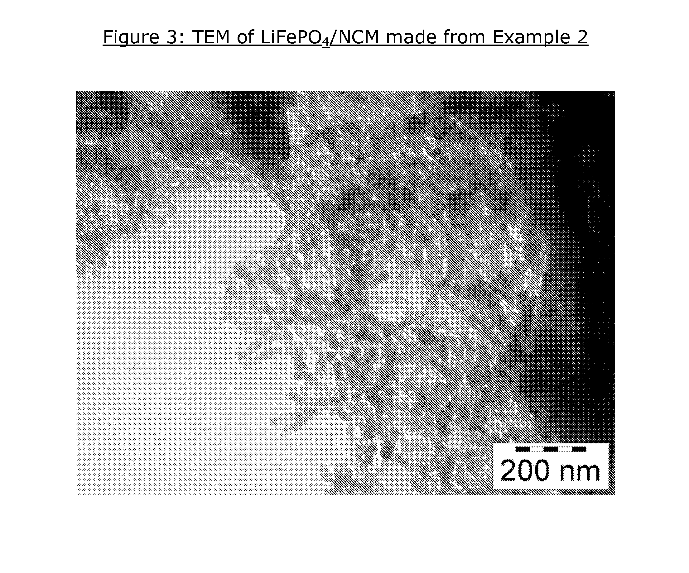
[0054]Li2CO3, NH4H2PO4 and FeC2O4.2H2O were mixed and ball-milled. A dispersing liquid, alcohol was added to form slurry which was ground for 6 hours through combined shaking and rotation actions. After milled, the is mixed slurry was dried to evaporate the alcohol in vacuum oven at 50° C. Then, the mixture was put in furnace and nitrogen was introduced at the flow rate of 50 ml / min and the temperature began to rise to the set temperature at the rate of 30° C. / min. When it arrived at the set point of 650-1000° C., the liquid petroleum gas was introduced into the tubular oven at the flow rate of 20 ml / min for 5-60 minutes. After that, the precursors were calcined at 500-900° C. under the nitrogen atmosphere for another 10-23 h. The product was cool down to room temperature under nitrogen atmosphere.

[0055]The synthesized LiFePO4 was mixed with Ni salt via slurry method and drying under vacuum at 60° C. The salts can be NiSO4, NiCl2 and Ni(NO3)2. In this example, the NiSO4 / LiFePO4 comp...

example 3

[0057]Li2CO3, NH4H2PO4, Ni particles and FeC2O4.2H2O were mixed and ball-milled by ZrO2 balls in a planetary micro mill. A dispersing liquid, alcohol was added to form slurry which was ground for 6 hours through combined shaking and rotation actions. After milled, the mixed slurry was dried to evaporate the alcohol in vacuum oven at 50° C. Then, the mixture was put in furnace and nitrogen was introduced at the flow rate of 50 ml / min and the temperature began to rise to the set temperature at the rate of 30° C. / min. When it arrived at the set point of 650-1000° C., a Ni mist was introduced to the furnace. The mist was produced from a 0.1˜2.0 M Ni solution (mixture of NiCl2 and NiSO4). The argon gas flow was turned off and ethylene as well as hydrogen gas where simultaneously introduced into the furnace at a flow rate of 100 ml / min each for 90 minutes. After that, the precursors were calcined at 500-900° C. under the nitrogen atmosphere for another 10-23 h. The product was cool down t...


PUM

PropertyMeasurementUnit
temperatureaaaaaaaaaa
electronic conductivityaaaaaaaaaa
temperatureaaaaaaaaaa

Abstract

The invention discloses a method for producing a carbon composite material, which includes the step of providing at least one carbon nanostructured composite material onto the surface of LiFePO4 particles to produce a LiFePO4 / carbon nanostructured composite material. The carbon nanostructured composite material is obtained by synthesizing at least one nanostructured composite material to form the carbon nanostructured composite material.

Description

FIELD OF INVENTION[0001]The present invention relates to a method for producing a carbon composite material.[0002]More particularly, the present invention relates to a method for producing a carbon composite material, namely a high capacity LiFePO4 / nanostructured carbon composite such as a cathode electrode active material for large scale Li-ion batteries.BACKGROUND TO INVENTION[0003]As the movement for environmental protection is increasingly dominant and the rapidly increasing price of oil is an undeniable reality, the automobile industry has been looking to introduce electric vehicles (EV), hybrid electric vehicles (HEV) and fuel cell vehicles (FCV), in place of conventional internal combustion vehicles as early as possible. In this regard, development of advanced batteries for application in transportation has become one of the top priorities due to the role of batteries as a critical technology for practical use of EV, HEV and FCV. Great strides in spreading battery powered veh...

Claims


Application Information

Patent Timeline
Patent Type & Authority Applications(United States)
IPC IPC(8): H01M4/525H01M4/583B05D5/12B05D3/02B82Y30/00
CPCH01M4/5825Y02E60/122H01M10/052Y02E60/10B82B3/00H01M4/139H01M4/583H01M10/05H01M10/0525
Inventor JI, SHANPASUPATHI, SIVAKUMARBLADER-GROEN, BERNARD JANLINKOV, VLADIMIR MIKHAILOVICH
Owner UNIVERSITY OF THE WESTERN CAPE
Learn More