Refinery desalter improvement

a desalter and refinery technology, applied in the direction of hydrocarbon dewatering, separation process, water treatment, etc., can solve the problems of less traditional low-gravity performance, difficult to develop new technologies, high cost and difficult implementation and testing, etc., to improve desalter performance, improve crude oil separation, and increase the capacity of conventional desalters

Active Publication Date: 2012-02-02
PHILLIPS 66 CO
View PDF10 Cites 48 Cited by
  • Summary
  • Abstract
  • Description
  • Claims
  • Application Information

AI Technical Summary

Benefits of technology

[0008]The current invention provides a process for separating crude oil from a refinery desalter rag layer by removing a rag layer stream from the desalter, feeding the rag layer stream to a disk stack centrifuge, separating water from crude oil, adding separated crude oil to the crude oil feed stream, and returning separated water to the desalter to improve crude oil separation and desalting. Using the disk stack centrifuge to separate the desalter rag layer into brine and desalted crude oil is an inexpensive way to increase the capacity of conventional desalters, allow refineries to process heavier oils, and improve desalter performance. The rag layer is quickly separated without requiring additional equipment, chemicals, or re-engineering of the refinery process.

Problems solved by technology

Unfortunately, the industry is averse to changes in technology and new technologies must be well established and proven before implementation.
Even with a need for better separation (Nnanna, 2008), developing new technologies is difficult, expensive and very hard to implement and test, especially on a scale comparable to the hundred thousand or more barrels-per-day required for even small refineries.
Standard desalters have worked well historically with the lighter, less viscous crude oils or for separation of solids from crude and shale oil sources, but their performance is challenged by less traditional low-gravity, high viscosity crude oil.
Traditional crude oil desalters have poor ionic salt removal as refineries process lower gravity / higher viscosity oils.
When working with unconventional oils, pilot scale desalting runs using electrostatic desalters, including electrostatic coalescence technology or electrocoagulation techniques and the Ohsol process for heavy oils were not effective.

Method used


Image

  • Refinery desalter improvement
  • Refinery desalter improvement
  • Refinery desalter improvement

Examples


experiment 1

MacKay River Heavy Crude Oil Process

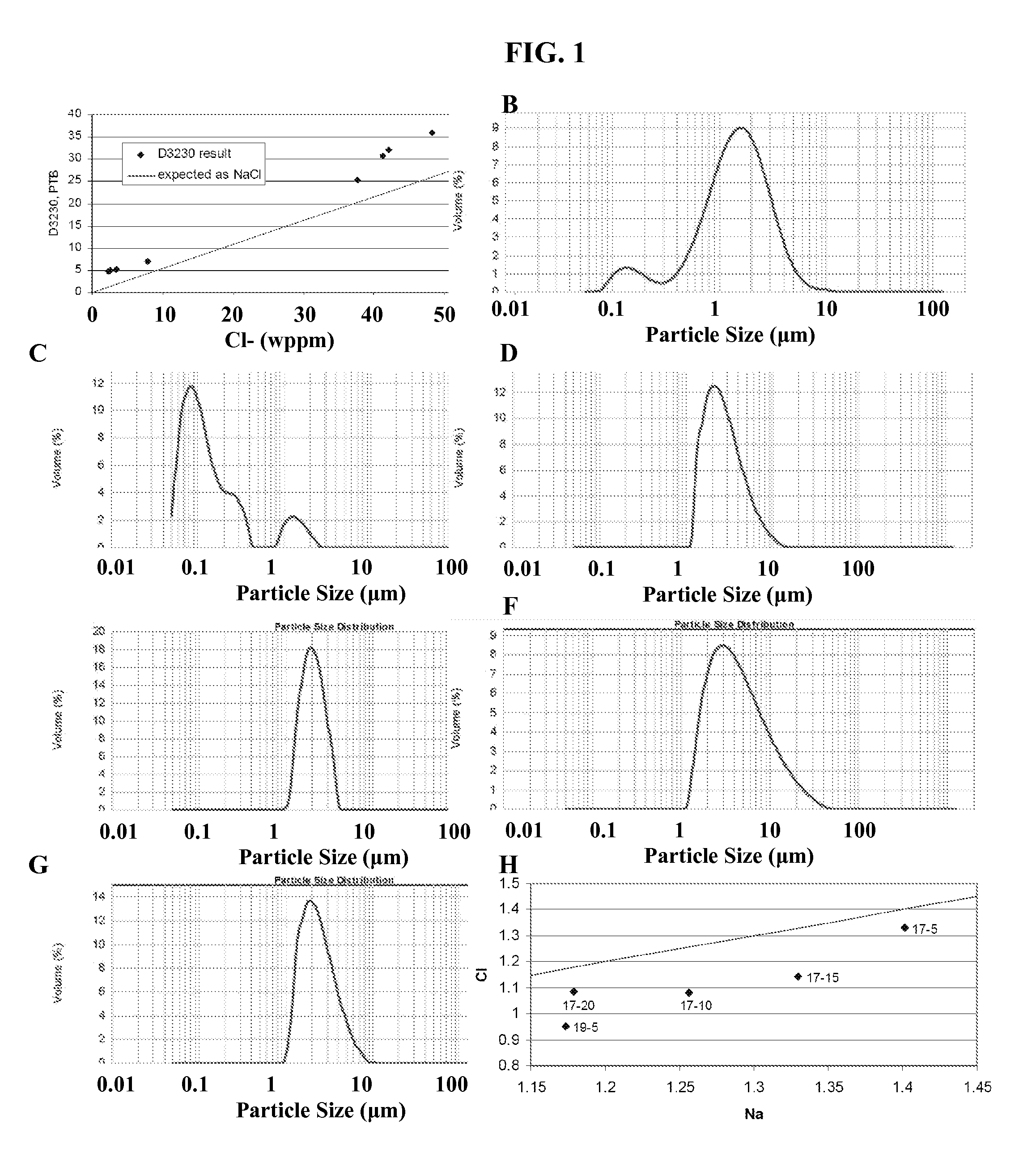
[0047]Initial assays were conducted on a small scale to demonstrate the concept and effectiveness of using stacked disk centrifuge to separate large volumes of crude oil rag layer for distillation and further processing. Approximately four drums of a MacKay River Heavy (MRH) crude oil blend with a gravity of 19.9° API were obtained from the Athabasca Terminal in Alberta, Canada and desalted using the stacked disk centrifuge system.

[0048]MRH was processed in a blend tank with a water / brine solution through an emulsion pump to replicate a rag layer emulsion as found in separator rag layers. MRH was fed to the blend tank with a water / brine from the water tank, the blended crude oil went through an emulsion pump. An emulsion pump exit line branching to a blend tank return line and a feed line, were fed into a stacked disk centrifuge desalting system with the feed line going through an optional steam driven heat exchanger to control temperature in the ...

example 2

Pilot Scale Western Canadian Select Heavy Crude Oil Process

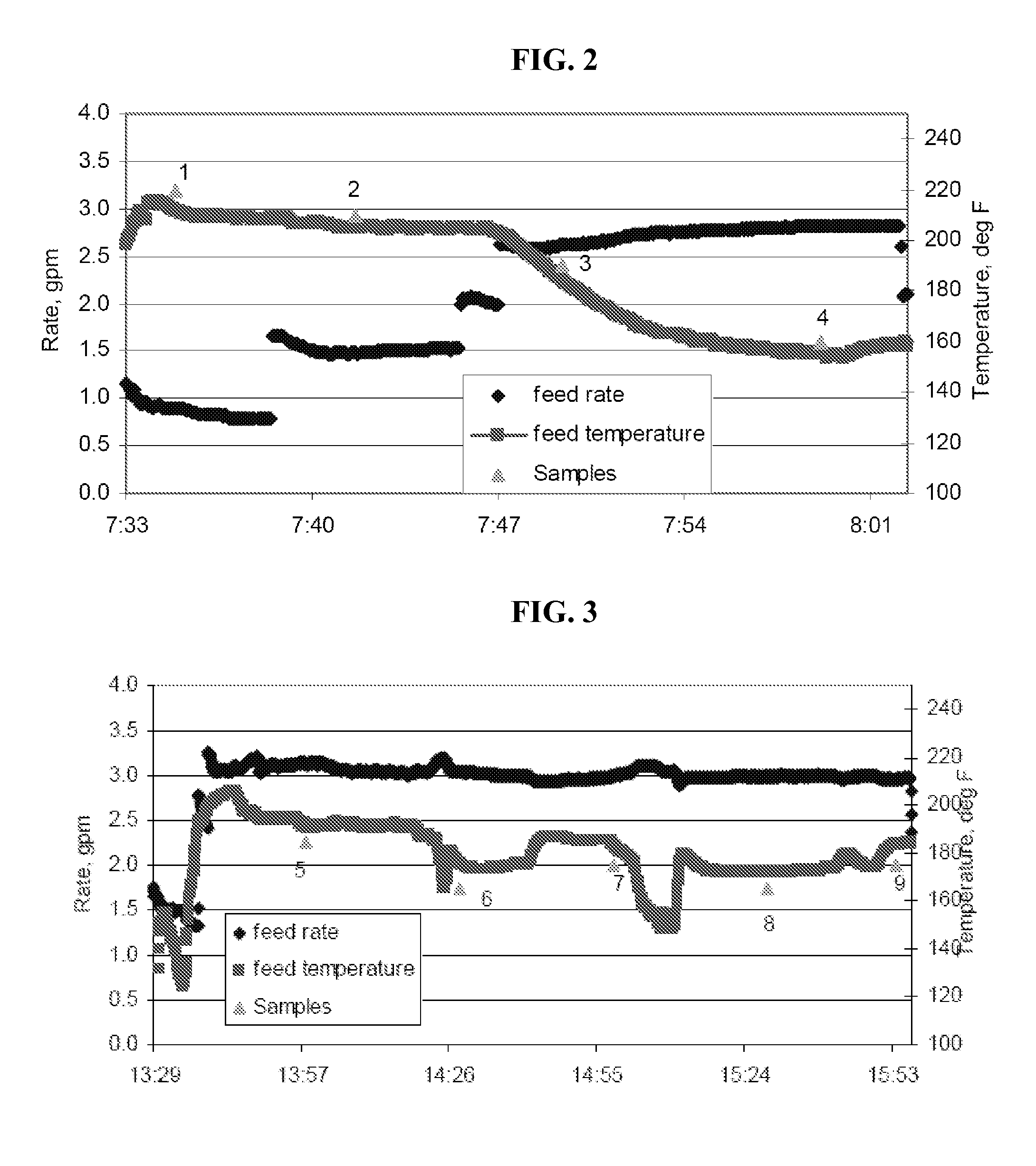
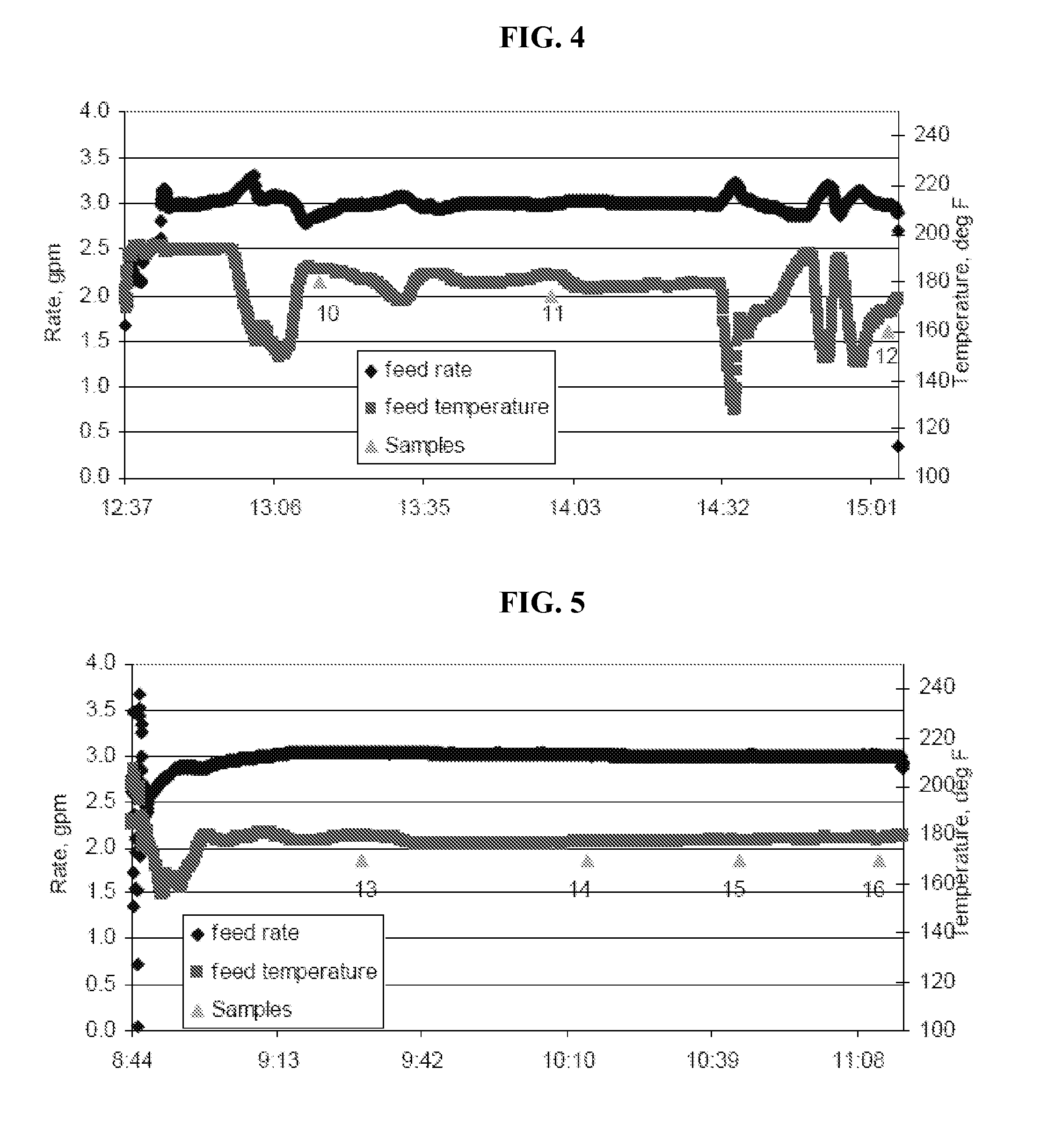
[0060]WCS crude oil blend had an API gravity very close to that of the MRH (20.4 API vs. 19.9 API). This report documents the successful desalting of 1,995 gallons of WCS crude oil blend to prepare it for fractionation and further pilot plant testing. As described above, desalting was accomplished using a blend tank with water and crude oil emulsion simulating a ‘rag layer’ fed to the stacked disk centrifuge system over the course of 5 operating days without the use of chemical additives. Chloride removal averaged 70 percent, ranging from 65 percent to 80 percent for the three composite product batches. Blend tank, emulsification pumps and a stacked disk centrifuge were used to effectively and economically desalt non-conventional crude oils without chemical addition.

[0061]Pilot scale equipment was used to generate batches of emulsion with deionized (DI) water and then to phase separate the water from the oil.

Emulsion Formati...

example 3

Commercial Scale Heavy Crude Oil Process

[0069]In one example, a commercial scale desalting system can have a separator tank with a clean crude outlet, wastewater outlet and rag layer outlet, the rag layer outlet feeds directly to a stacked disk centrifuge operating at a rate required to keep the rag layer height fairly constant preventing rag layer contamination of wastewater and oil feedstreams. The stacked disk centrifuge can separate the oil and water emulsion at a rate of greater than 3 gpm, sufficient to process the rag layer produced in a conventional refinery separator. If a greater processing capacity is required, additional stacked disk centrifuges or larger stacked disk centrifuges may be used to process the rag layer at a greater rate. If a higher level of separation is required, contaminants are still present in the clean crude oil, then additional stacked disk centrifuges may be used. Separated water may be fed into numerous water systems on the refinery including back ...


PUM

PropertyMeasurementUnit
temperatureaaaaaaaaaa

Abstract

The invention relates to improved methods of desalting hydrocarbon feeds using a separator with a stacked disk centrifuge to separate an emulsified oil and water rag layer. This method is effective for desalting heavy, high ionic, and non-traditional crude oils.

Description

CROSS-REFERENCE TO RELATED APPLICATIONS[0001]This application is a non-provisional application which claims benefit under 35 USC §119(e) to U.S. Provisional Application Ser. No. 61 / 368,103 filed Jul. 27, 2010, entitled “REFINERY DESALTER IMPROVEMENT,” which is incorporated herein in its entirety.STATEMENT REGARDING FEDERALLY SPONSORED RESEARCH[0002]None.FIELD OF THE INVENTION[0003]This invention relates to improved methods of desalting hydrocarbon feeds using a stacked disk centrifuge to separate an emulsified oil and water rag layer. This method is effective for desalting heavy, high ionic, and non-traditional crude oil sources.BACKGROUND OF THE INVENTION[0004]Desalting crude oils is a two step process—creating a fine dispersion or emulsion of fresh water and the oil, and then effecting a phase separation of the water from the oil. Smaller water droplets provide more area for mass transfer of ionic contaminants (mostly chloride salts) from the oil into the water than large droplets...

Claims


Application Information

Patent Timeline
Patent Type & Authority Applications(United States)
IPC IPC(8): C10G31/10
CPCB01D17/0217B01D17/041B01D21/009B01D21/262B01D2221/04C10G2300/805C10G31/08C10G31/10C10G33/06C10G2300/1033C10G7/04C10G53/02
Inventor LOVE, SCOTT D.
Owner PHILLIPS 66 CO
Why Eureka
Try Eureka