

Hydrogen generation
a technology of hydrogen generation and hydrogen gas, applied in the field of electrolysis of water, can solve the problems of hazard, risk of gas migration, manifest hydrogen production efficiency, etc., and achieve the effect of increasing efficiency
- Summary
- Abstract
- Description
- Claims
- Application Information
AI Technical Summary
Benefits of technology
Problems solved by technology
Method used
Image

Examples
Embodiment Construction
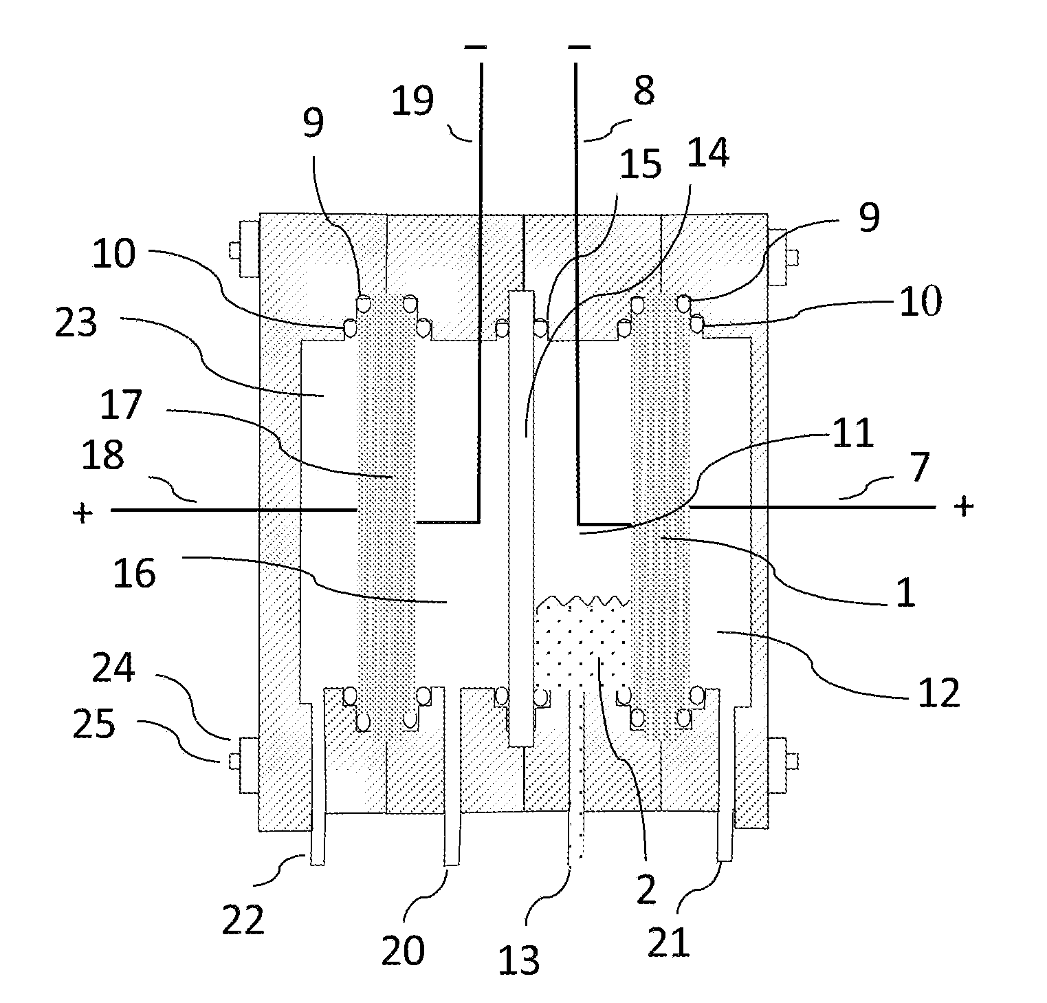
[0017]Embodiments of the present invention enable electrochemically produced hydrogen to be dried not only more efficiently, but also so as to eliminate the need for condensate removal. Embodiments of the present invention confer an increased efficiency on a hydrogen electrolyser, and afford a diagnostic for monitoring the dryness of hydrogen produced by the water generator.
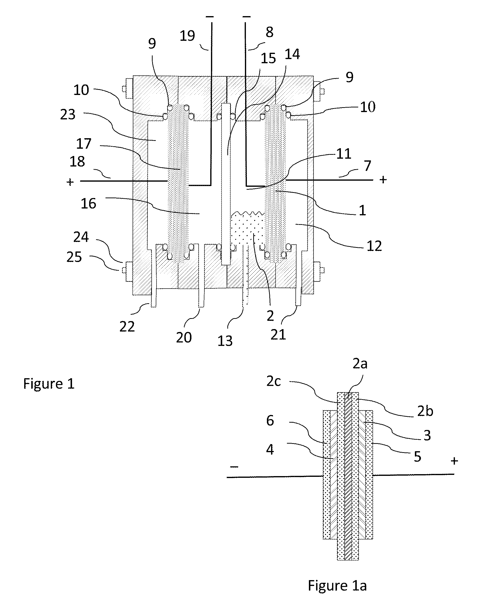
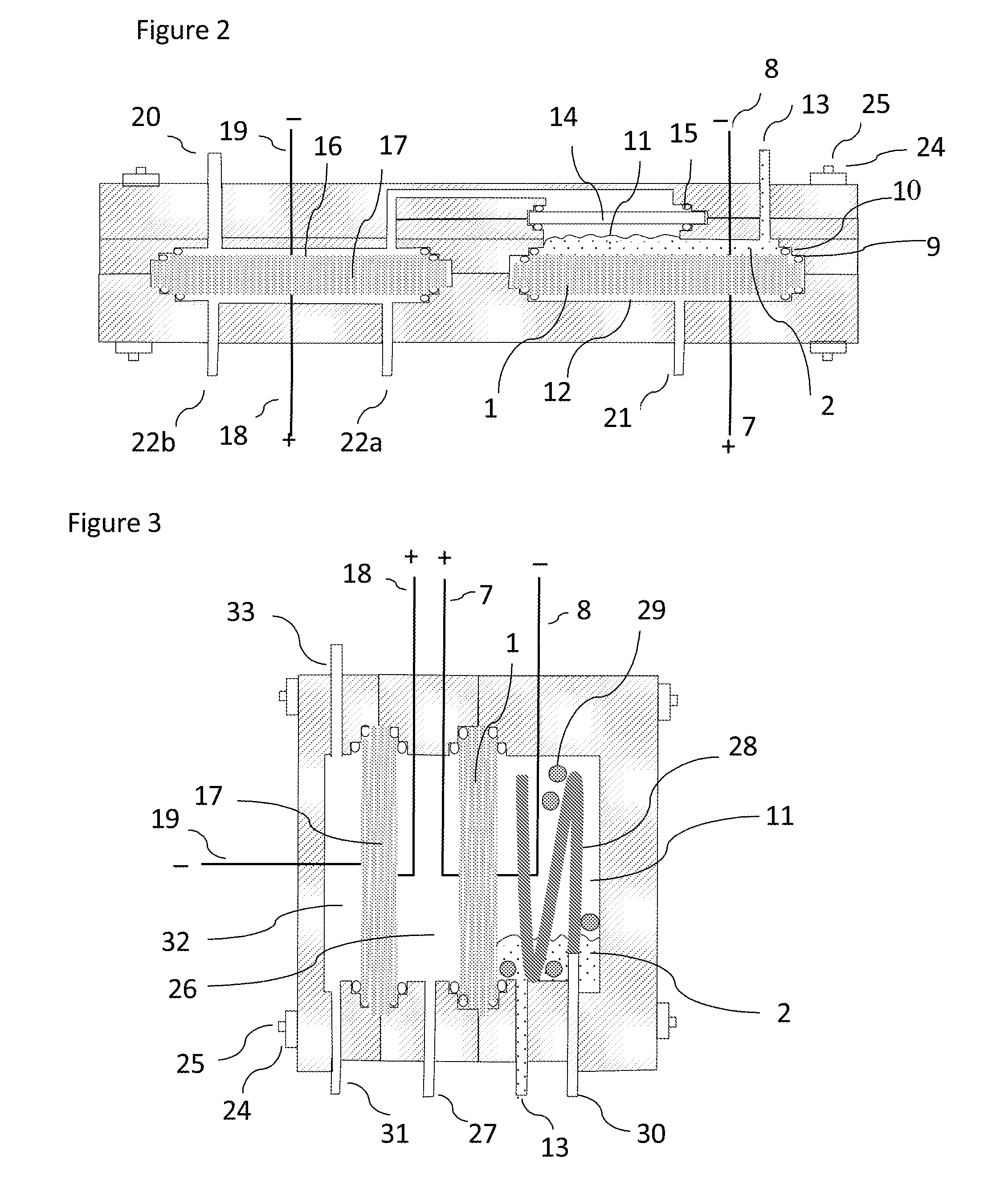
[0018]According to one aspect of the present invention, there is provided a hydrogen generator which includes a cascade of at least two electrolytic cells, each comprising a membrane electrode assembly incorporating a solid polymer electrolyte polarized so as to generate hydrogen from water at a cathode and oxygen at an anode, in which the membrane electrode of a first cell is at least partially exposed on one or both sides to a supply of liquid water and the hydrogen produced in this cell contacts the cathode surfaces of the or each successive electrolytic cell, wherein any water entrained in or carried over wit...
PUM
| Property | Measurement | Unit |
|---|---|---|
| size | aaaaa | aaaaa |
| voltage | aaaaa | aaaaa |
| electric potential | aaaaa | aaaaa |
Abstract
Description
Claims
Application Information