
Dehydration of liquid fuel

Inactive Publication Date: 2012-02-09
AIRBUS OPERATIONS LTD
View PDF13 Cites 33 Cited by
  • Summary
  • Abstract
  • Description
  • Claims
  • Application Information

AI Technical Summary

Benefits of technology

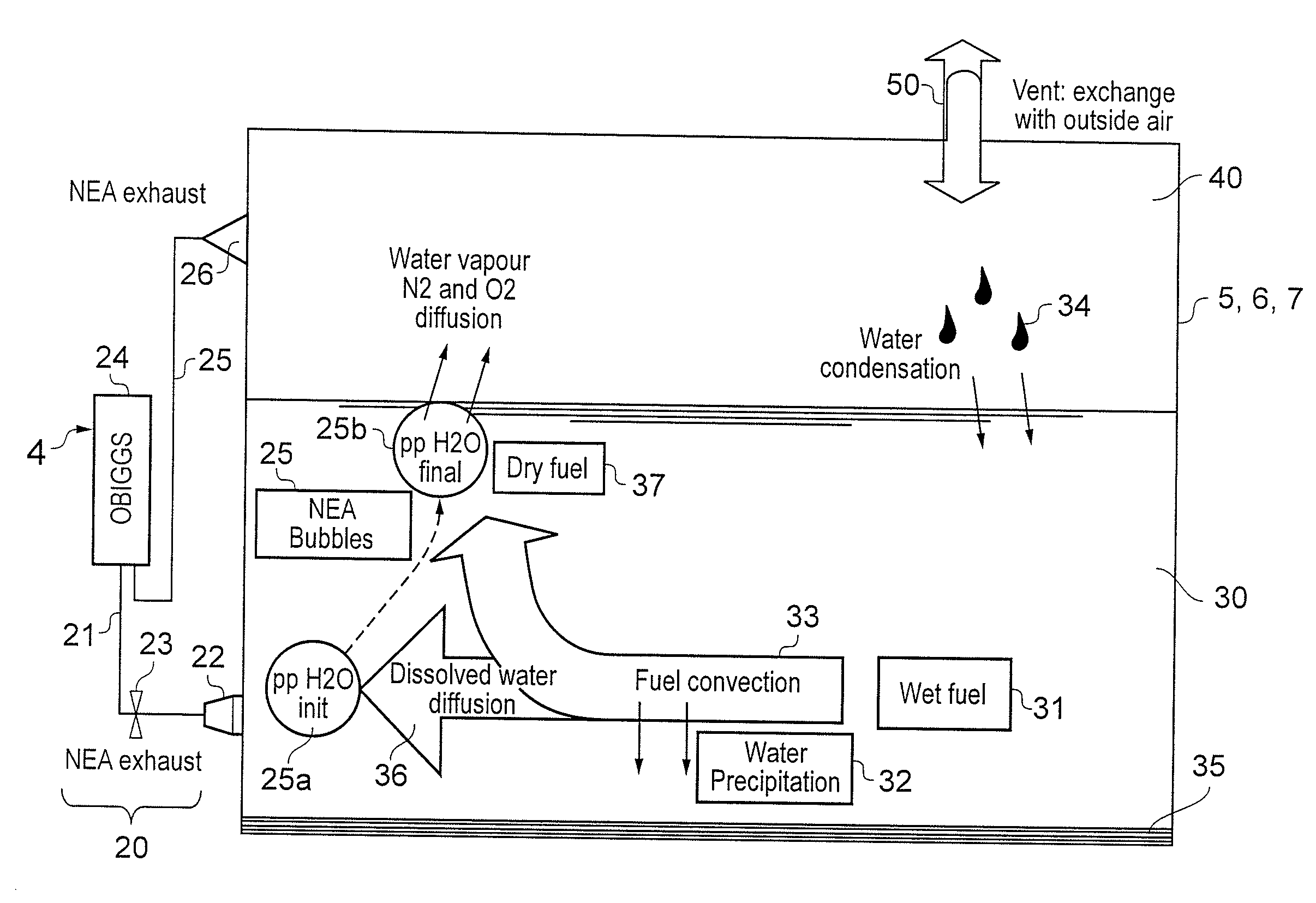
[0009]The invention is advantageous in that the dry gas injected into the fuel forms bubbles, which rise through the fuel, and diffusion of water from the fuel into the gas occurs until equilibrium is reached. By reducing the concentration of dissolved water in the fuel, there is a reduction in the amount of water that can precipitate out of the fuel due to, e.g. a decrease in fuel temperature.
[0022]Since the fuel level, and pressure, within a fuel tank is subject to change, a vent system is typically employed that vents the fuel tank ullage to the ambient atmosphere in order to equalise pressure between the interior and the exterior of the fuel tank. When there is a net inflow of air through the vent system into the fuel tank ullage, unwanted moisture may enter the fuel system. In the case of an aircraft fuel tank, this can be a particular issue during descent when there is typically a net inflow of humid air into the tank, which could cause unwarranted condensation on cold surfaces within the fuel tank. This invention may also be used to address this issue by injecting an sufficient volume flow rate of the dry gas into the fuel such that there is a minimal, zero, or negative net inflow of air through the fuel tank vent system. The system may therefore include a “high” flow mode. In addition to reducing the water content within the fuel tank, the high flow of inert gas may be used to ensure there is an inert atmosphere within the fuel tank ullage. It may be preferable to have a net outflow from the ullage to ambient to vent the moisture in the fuel picked up by the dry gas to the ambient. This is to ensure the water is removed from the system.
[0023]Since the concentration of water within the fuel will reduce owing to operation of this invention, the concentration of water within the fuel is likely to be highest at the start of injecting the dry gas into the fuel. The rate of water diffusion from the fuel into the gas may therefore be highest at the start of operations, which could lead to a temporary increase in the relative humidity in the fuel tank ullage. This may be undesirable as condensation may form on the fuel tank walls. To combat this, the rate of gas flow injected into the fuel may be controlled so as to increase slowly at start-up. In addition, it may be operated in a high flow mode such that there is a net outflow from ullage to ambient to drive out the moisture from the system.

Problems solved by technology

Water is an unavoidable contaminant in fuel.
Water can affect components in fuel systems and lead to operational delays and increased maintenance activities.
Although water may affect fuel systems of land or water based vehicles, water is a particular problem in aircraft fuel systems.
However, since the solubility of water in fuel decreases with decreasing temperature, during cruise water from dissolution (rejection of dissolved water from fuel) can form droplets of the order of microns suspended within the fuel.
Pooled free water can be drained off when the aircraft is on the ground but this is time consuming and costly, leading to a loss of operational efficiency.
At sufficiently cold temperatures the free water can freeze, which can require a further significant maintenance operation of heating the aircraft in a hangar in order to perform the water drain activity.

Method used


Image

  • Dehydration of liquid fuel
  • Dehydration of liquid fuel
  • Dehydration of liquid fuel

Examples


Embodiment Construction

)

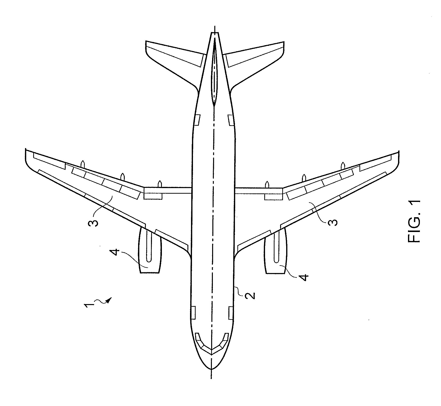
[0032]FIG. 1 illustrates a plan view of an aircraft 1, such as a commercial airliner, comprising a fuselage 2, a wing 3 and under wing mounted engines 4. The interior volume of the wing 3 is used as fuel tanks for storing liquid hydrocarbon aviation fuel, such as Jet A-1. The aircraft 1 has a three tank configuration, which forms part of an aircraft fuel system.

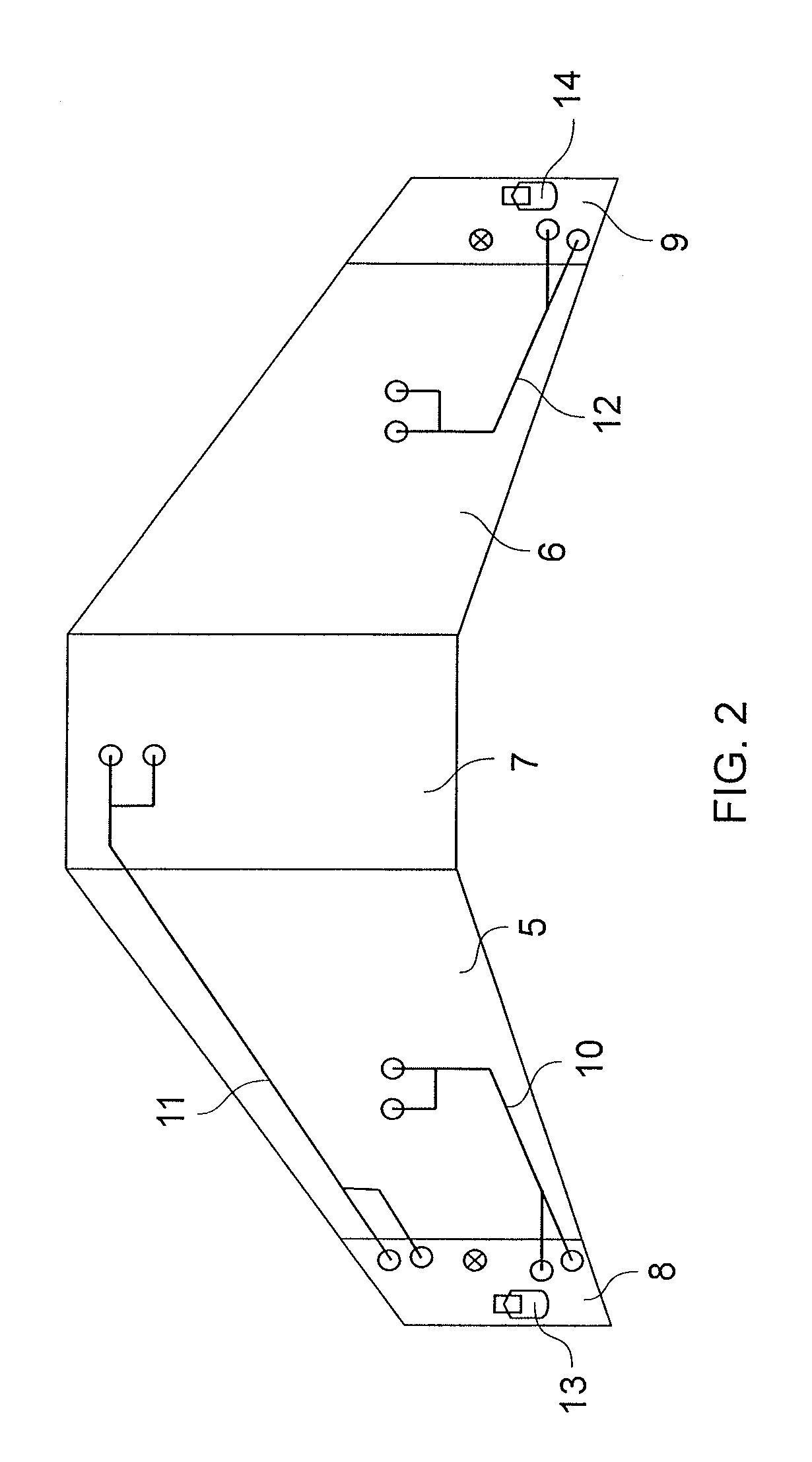
[0033]FIG. 2 illustrates schematically the three tank configuration which comprises a left wing tank 5, a right wing tank 6 and a centre tank 7. The aircraft fuel system further comprises a ventilation system for ventilating the ullage of each of the fuel tanks 5, 6, 7. The ventilation system includes a left vent tank 8 and a right vent tank 9 disposed at the tips of the wing 3. The vent tank 8 ventilates the left wing tank 5 by means of ventilation pipe 10, and also ventilates the centre tank 7 by means of ventilation pipe 11. The right vent tank 9 ventilates the right wing tank 6 by means of ventilation pipe 12. Each vent ...


PUM

PropertyMeasurementUnit
Temperatureaaaaaaaaaa

Abstract

A method for dehydrating liquid fuel, the method comprising injecting a supply of dry gas into a liquid fuel via an outlet submerged in the liquid fuel. Also, a system for dehydrating liquid fuel, the system comprising a container for storing a liquid fuel, a line for delivering a supply of dry gas, and an outlet disposed near the bottom of the container and connected to the gas line for injecting dry gas into the liquid fuel.

Description

RELATED APPLICATIONS[0001]The present application is based on, and claims priority from, British Application Number 1012988.0, filed Aug. 3, 2010, the disclosure of which is hereby incorporated by reference herein in its entirety.FIELD OF THE INVENTION[0002]The present invention relates to a system and method for dehydrating liquid fuel.BACKGROUND OF THE INVENTION[0003]Water is an unavoidable contaminant in fuel. Water can affect components in fuel systems and lead to operational delays and increased maintenance activities. In addition, the propensity for microbiological contamination is directly proportional to the presence of water and the temperature within fuel tanks.[0004]Although water may affect fuel systems of land or water based vehicles, water is a particular problem in aircraft fuel systems. Water may enter aircraft fuel tanks from fuel loaded into the aircraft fuel tanks during refuel (dissolved water) and from air entering the aircraft fuel tanks via its vent system. A ...

Claims


Application Information

Patent Timeline
IPC IPC(8): C07C7/00B64D37/02B64D37/06B01F3/04
CPCB64D37/34Y02T50/44C10L2270/04C10L2230/14C10L2290/08C10L1/08C10L2290/145C10L2290/141C10L2200/043Y02T50/40
Inventor LAM, JOSEPH K-WLAWSON, CRAIG P.WETTERWALD, MARC
Owner AIRBUS OPERATIONS LTD
Learn More