Eureka AIR delivers breakthrough ideas for toughest innovation challenges, trusted by R&D personnel around the world.

Cable-stayed rotor for wind and water turbines

a fluidflow turbine and rotor technology, applied in the direction of rotors, marine propulsion, vessel construction, etc., can solve the problems of fatigue life, large blades, and structural limitations of the length to which typical blades may be extended, and achieve the effects of less cost, convenient blade transportation, and greater performan

Inactive Publication Date: 2012-03-01
CLIPPER WINDPOWER INC
View PDF4 Cites 12 Cited by
  • Summary
  • Abstract
  • Description
  • Claims
  • Application Information

AI Technical Summary

Benefits of technology

[0016]The advantage of this structure is that the blade pitch motors can be located at the hub assembly (main hub), reducing strain on the rotor. The motor at the main hub can turn the inner and outer blade sections to capture wind across the entire structure.
[0018]The invention has the advantage that cable stays allow for many narrow, high aspect ratio blades to be used on a fluid-flow turbine rotor. This results in greater performance and smaller, less costly and easy to transport blades.
[0019]The invention has the advantage that fore and / or aft stays provide resistance to the rotor's thrust forces and can assist in transmitting the rotor torque to the hub, the blade-to-blade stays resist the “lead-lag” loads.
[0020]The invention has the advantage that it provides a structural means to support blades efficiently on very large rotors which would otherwise exceed the structural capacity of typical rotors where blades are simply attached to the hub with no other means of structural support.
[0021]The invention has the advantage of reduced cost and increased efficiency of large-scale wind and water turbines.

Problems solved by technology

There are structural limitations to the length to which typical blades may be extended.
A key structural limitation on very large blades is with fatigue life at the root of the blade where the gravity effect on each rotation produces lead-lag loading, concentrated on the blade root.
Thus, there are definite scaling limitations to increasing the size of conventional rotors.
Excessive hunting motion results in undesirable yaw-induced vibration and stress on the rotor system.
Blade and rotor hub fatigue and ultimate failure of the blade and rotor hub where the blade and rotor hub meet is directly related to the number of hunting motions and the speed at which they occur.
Vibration and stress cause fatigue in the rotor hub and blade root thereby decreasing the useful life of the equipment and reducing dependability.
As wind turbine rotor size increases in the multi-megawatt size range, blade length imposes structural requirements on the blade root end, which adds weight, which in turn imposes even greater structural requirements, which in the end limits blade up-scaling possibilities.

Method used


Image

  • Cable-stayed rotor for wind and water turbines
  • Cable-stayed rotor for wind and water turbines
  • Cable-stayed rotor for wind and water turbines

Examples


Embodiment Construction

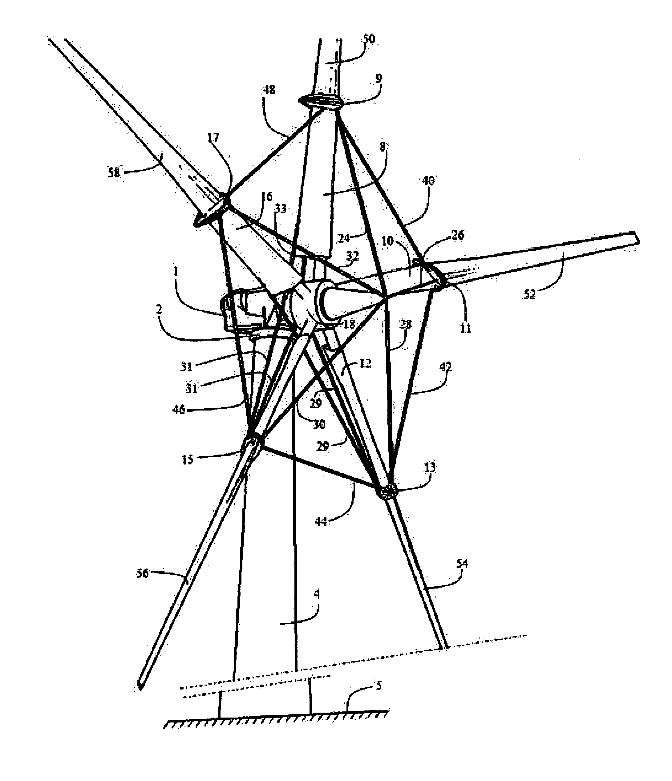
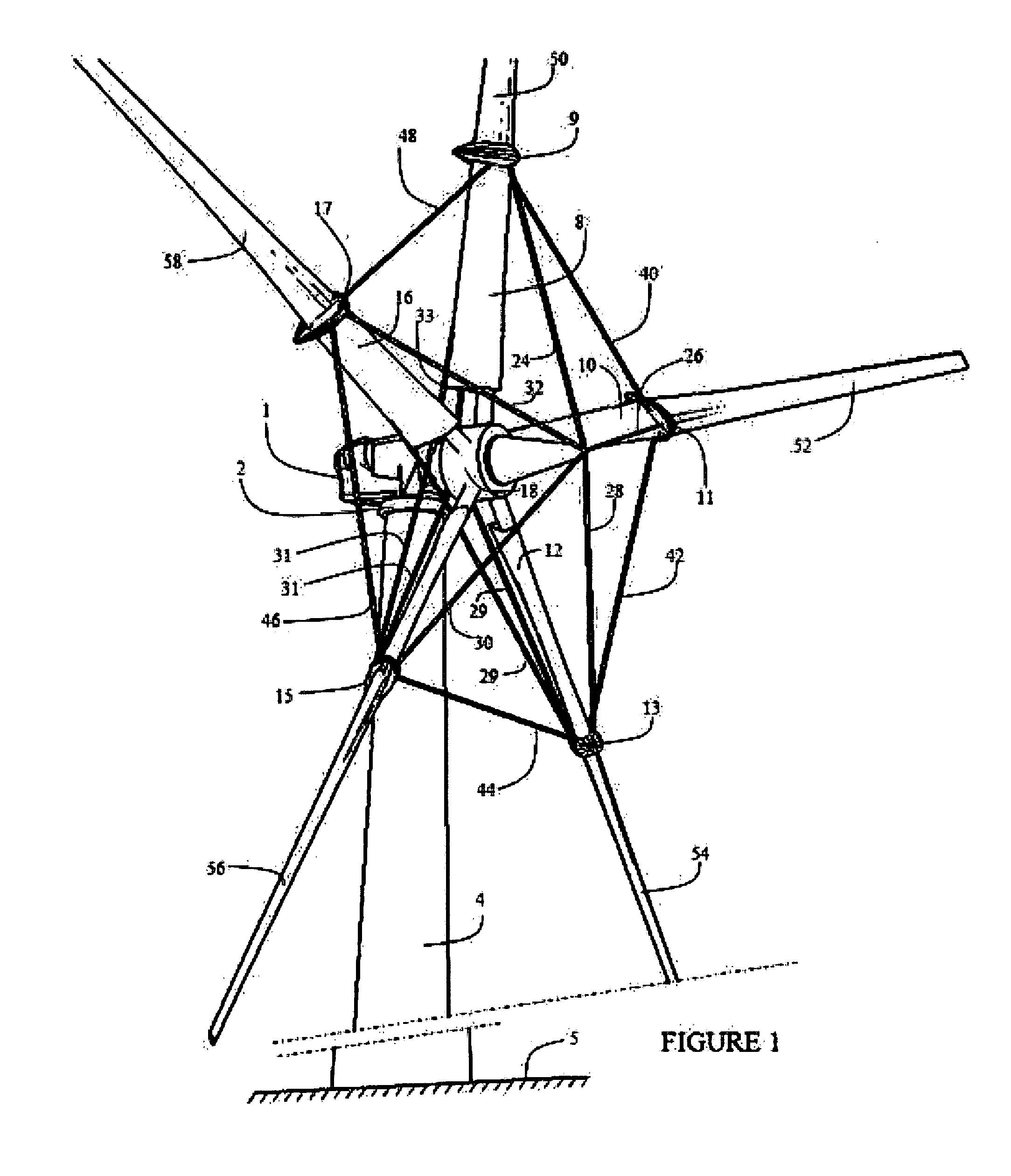
[0028]Refer to FIG. 1, which is a perspective view of a rotor system with linked, rotating inner and outer blade sections in which applicant's invention is embodied. The wind power-generating device includes an electric generator housed in a turbine nacelle 1, which is mounted to a turbine yaw base 2 atop a tower structure 4 anchored to the ground 5. The turbine yaw base 2 is free to rotate in the horizontal plane such that it tends to remain in the path of prevailing wind current. The rotor system has a hub assembly 6, which includes inner blade sections 8, 10, 12, 14, 16 attached to a hub 18. Each inner blade section is provided with a collar 9, 11, 13, 15, 17, respectively. The hub assembly consists of hub structure extending fore and aft of where the blades are attached to the hub. The inner blade sections 8, 10, 12, 14, 16 extend from the hub structure.

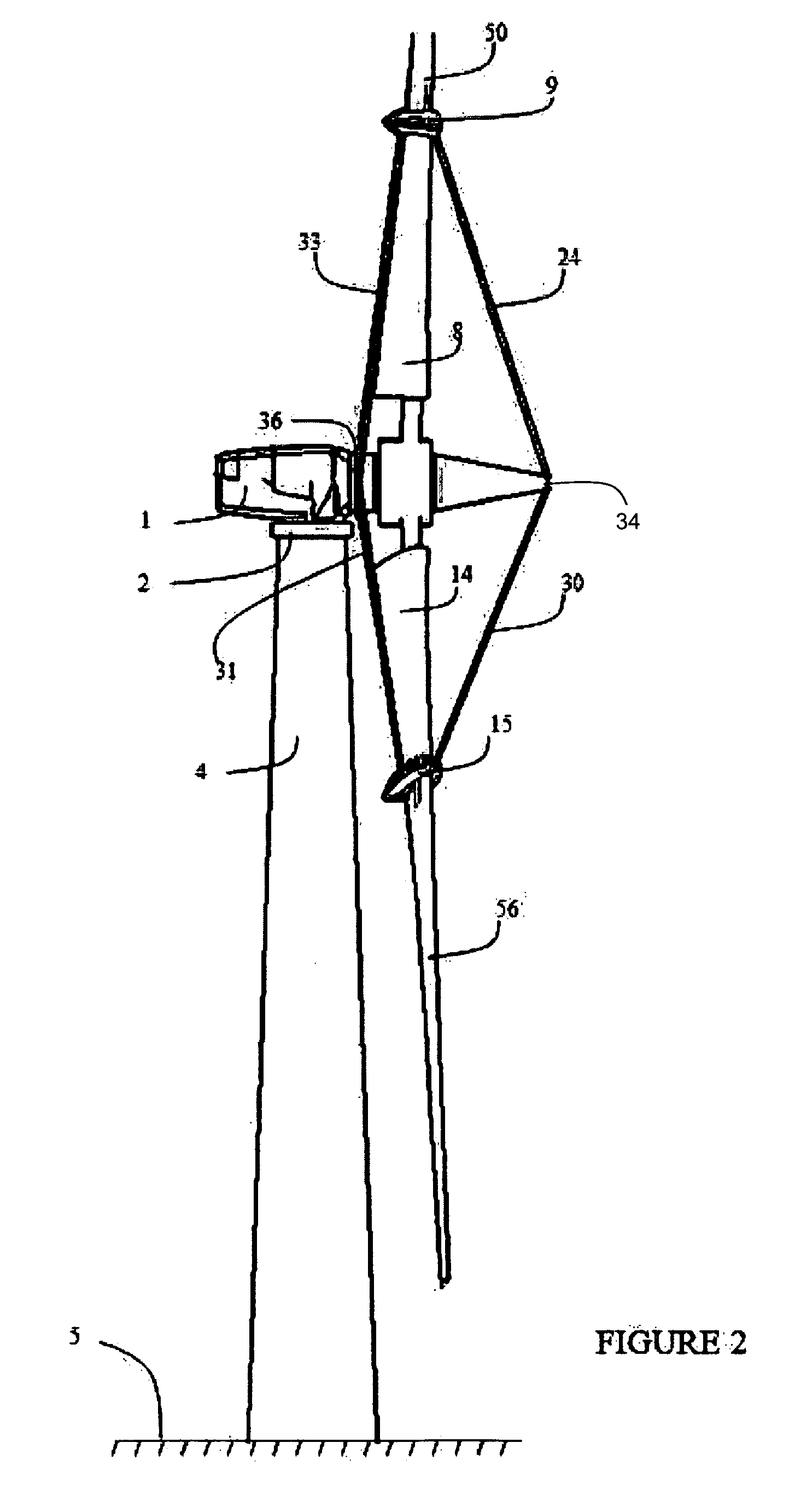
[0029]Refer to FIG. 2. The inner blade sections 8, 10, 12, 14, 16 are further mounted in the hub assembly by a plurality of for...


PUM


Abstract

A rotor system for a fluid flow turbine includes a hub assembly which is mounted on a shaft coupled with a power transmitting device and a plurality of rotor blades. Each rotor blade includes an inner blade section and an outer blade section, wherein the inner blade section is supported by and extends outwardly from the hub assembly and the outer blade section extends outward from the inner blade section. Each of the rotor blades includes a collar to accommodate the inner blade section and / or the outer blade section such that the inner blade section and the outer blade section are rotatable for pitch control. Pitch motors are located at the hub assembly and dependently or independently pitch the inner blade sections and the outer blade sections.

Description

BACKGROUND OF THE INVENTION[0001]1. Field of the Invention[0002]The invention relates to a rotor system for a fluid-flow turbine comprising a hub mounted on a shaft, and a plurality of rotor blades.[0003]2. Prior Art[0004]In a typical horizontal-axis wind turbine, a nacelle is mounted on a tall vertical tower. The nacelle houses power-transmitting mechanisms, electrical equipment and supports a rotor system at one end. Rotor systems for horizontal-axis wind turbines ordinarily include one or more blades attached to a rotor hub on a shaft. Wind flow drives the rotor, which turns the shaft in the nacelle. The shaft turns gears that transmit torque to electric generator(s). The nacelle typically pivots about the vertical tower to take advantage of wind flowing from any direction. The pivoting about this vertical-axis in response to changes in wind direction is known as yawing or yaw response and the vertical-axis is referred to as the yaw-axis. As wind moves past the blades with enough...

Claims


Application Information

Patent Timeline
IPC IPC(8): F04D29/36
CPCF03D1/0658F03D7/0224F03D7/0228Y02E10/728F05B2260/79Y02E10/721Y02E10/723F05B2240/917Y02E10/72
Inventor DEHLSEN, JAMES G.P.BROWN, MATTHEWGLUCK, KENNETH
Owner CLIPPER WINDPOWER INC
Why Eureka
Eureka Blog
Learn More