Check patentability & draft patents in minutes with Patsnap Eureka AI!

Method to treat produced waters from thermally induced heavy crude oil production (tar sands)

Inactive Publication Date: 2012-03-08
GENERAL ELECTRIC CO
View PDF4 Cites 33 Cited by
  • Summary
  • Abstract
  • Description
  • Claims
  • Application Information

AI Technical Summary

Benefits of technology

[0007]In one aspect, the invention is directed to a method of treating a produced water stream from oil recovery operations having a temperature between 160° F. (71° C.) and 200° F. (93° C.) and containing high concentrations of soluble and insoluble organic and inorganic contaminants. The process includes passing the produced water stream to a pretreatment phase to obtain a filtered produced water stream, wherein the produced water stream is subjected to a pH adjustment, wherein the pH of the pH adjusted produced water stream is less than 6.0. The filtered produced water stream is then passed to an ultrafiltration (UF) phase to recover an ultrafiltration permeate having reduced oil and suspended solids. Th

Problems solved by technology

The disposal of this oil field produced wastewater is problematic due to the presence of relatively high concentrations of organics, silica, boron, hardness, suspended and dissolved solids.
With increasing water quality standards, surface discharge of the produced water has become even more problematic and has produced a need for methods to treat the produced water prior to discharge.
Unfortunately, the contaminants present in produced water vary depending upon its origin and the particular characteristics of the oil well site.
This has made the standardization of water treatment facilities difficult.
However, the recovery across reverse osmosis systems is often limited by scaling due to silica or fouling due to organics.
That is, high concentrations of silica in the feed water tend to scale the reverse osmosis membranes due to the concentration of silica exceeding solubility limits.
Organics that exceed solubility limits also tend to foul the reverse osmosis membranes.
Scaling due to silica and fouling due to organics can cause substantial down time of the reverse osmosis unit or units, requiring frequent cleaning, replacement and maintenance.
These contaminants are often present in the form of weakly ionized salts, sicilic acid and boric acid, and generally, reverse osmosis membranes are not efficient in rejecting such weakly ionized salts.

Method used


Image

  • Method to treat produced waters from thermally induced heavy crude oil production (tar sands)
  • Method to treat produced waters from thermally induced heavy crude oil production (tar sands)

Examples


example 1

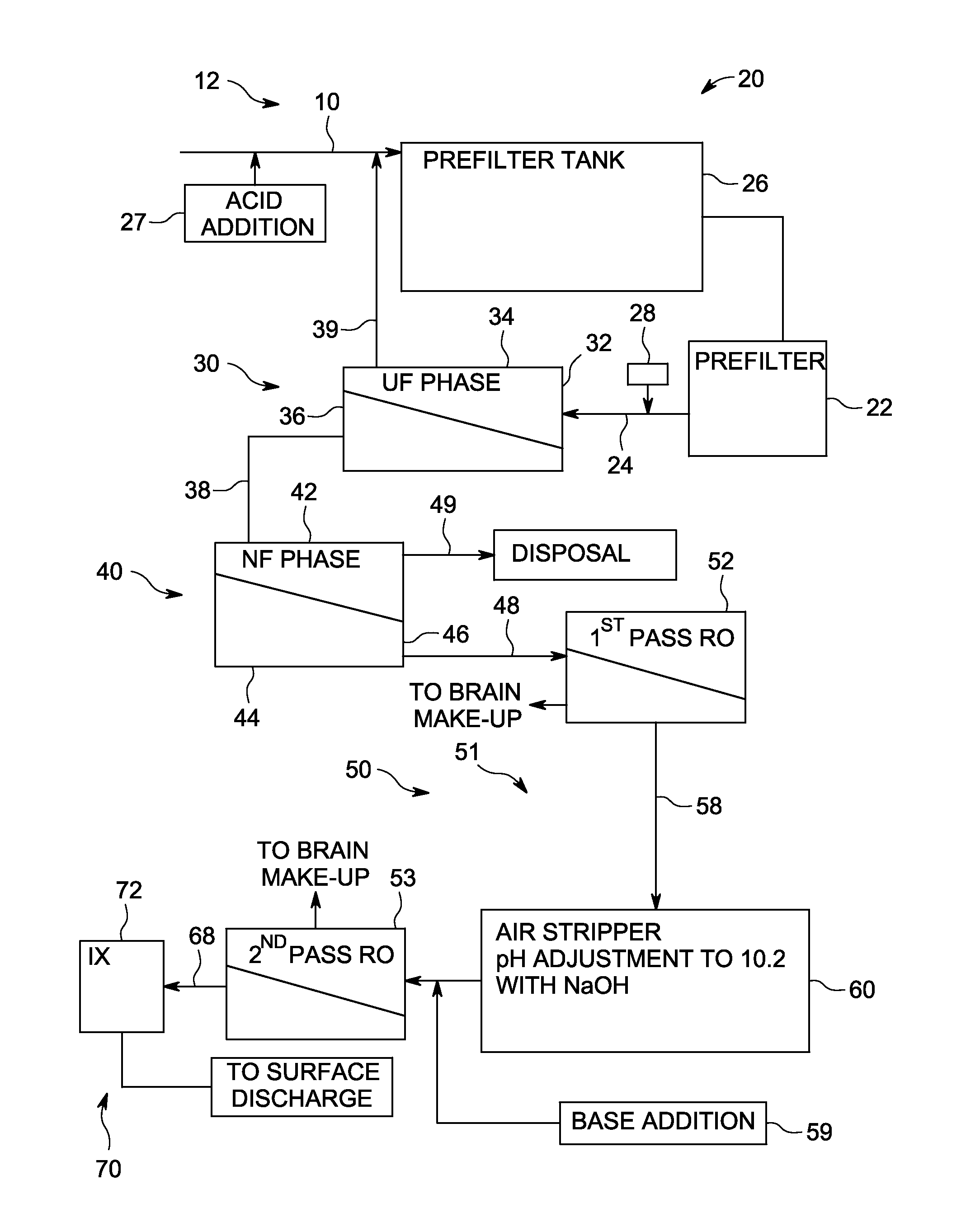
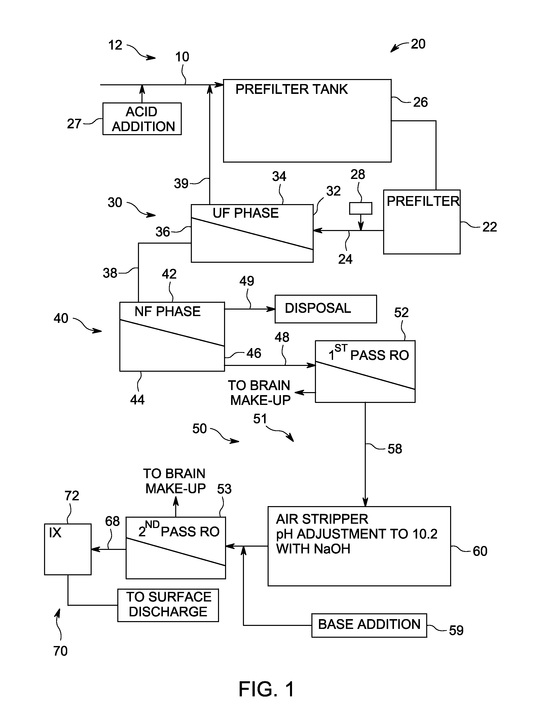
[0030]A produced water stream from oil recovery operations containing high concentrations of contaminants was subject to oil separation and passage through a produced water treatment system 12 using a multiple membrane technology approach. The produced water stream had a temperature of 185° F. (85° C.). The produced water stream contained high levels of salts (about 10,000 ppm), oil (2SO4 was added per 1000 gallons of produced water as feed. A 50 micron cartridge filter was used in the prefiltration stage.

[0031]The flow rate to the UF phase and the NF phase was 20 GPM. The UF phase used four 8 inch×40 inch (20 cm×102 cm) model MW8040CJL elements. The NF phase used four 8 inch×40 inch (20 cm×102 cm) model DK8040CJO elements. The NF permeate was fed directly to a high temperature Osmonics 80B first-pass RO system and the subsequent second-pass low-pressure brackish water RO system. These RO systems used eight 4 inch×40 inch (10 cm×102 cm) elements. The average operating temperature fo...

example 2

[0039]A produced water stream from oil recovery operations containing high concentrations of contaminants was subject to oil separation and passage through a produced water treatment system 12 using a multiple membrane technology approach. A 75 micron cartridge filter was used in the prefiltration stage. The average operating temperature for the UF phase, the NF phase and the RO phase was 165° F. (73° C.). The UF phase had a net driving pressure (NDP) of about 20 PSI and 100% recovery. The UF permeate was saturated in silica at 2780 ppm. The NF phase had a net driving pressure (NDP) of about 200 PSI and greater than 90% recovery. The NF permeate had hardness less than 2 ppm, TDS of 1180 ppm and saturated in silica. A single pass RO system was used operating at 300 PSI and greater than 90% recovery. The treated make-up water had less than 20 ppm TDS, less than 1 ppm silica and less than 0.2 ppm hardness.

example 3

[0040]A produced water stream from oil recovery operations containing high concentrations of contaminants was subject to oil separation and passage through a produced water treatment system 12 using a multiple membrane technology approach. The prefiltration stage used a free oil knock-out tank, induced gas floatation, a walnut shell filter and a 25 micron cartridge filter. The average operating temperature for the UF phase, the NF phase and the RO phase was 165° F. (73° C.). The UF phase had a net driving pressure (NDP) of about 30 PSI. The UF permeate was saturated in silica at 2780 ppm. The NF phase had a net driving pressure (NDP) of about 160 PSI and greater than 90% recovery. The NF permeate had hardness less than 2 ppm, TDS of 484 ppm, and silica of 212 ppm. A single pass RO system was used operating at 300 PSI and greater than 92% recovery. The treated make-up water had less than 25 ppm TDS, less than 3 ppm silica and less than 0.2 ppm hardness.


PUM

PropertyMeasurementUnit
Temperatureaaaaaaaaaa

Abstract

A method for treating oil field produced wastewater containing high organics, silica, boron, hardness, and suspended and dissolved solids by applying three membrane types in series is provided. First, Ultrafiltration (UF) is applied to remove oil and suspended solids. Second, Nanofiltration (NF) is used to reject hardness, soluble iron and organics. Subsequently, the NF permeate is treated by a double pass Reverse Osmosis (RO) process. The first-pass is applied at a high temperature of about 180° F. and low pH to remove the majority of the salts and silica. Then the feed is chilled, stripped of carbon dioxide and finally pH adjusted to 10 to maximize boron removal.

Description

BACKGROUND OF THE INVENTION[0001]1. Field of the Invention[0002]This invention relates generally to a method for treating oil field produced wastewater containing high organics, silica, boron, hardness, and suspended and dissolved solids, and more particularly to a method for treating the wastewater to a level sufficient to meet requirements to discharge the treated water.[0003]2. Description of Related Art[0004]One method used to improve recovery of viscous or heavy crude oil involves injecting steam into an oil deposit resulting in the recovery of an oil / water mixture. The water is then removed from this oil / water mixture. The disposal of this oil field produced wastewater is problematic due to the presence of relatively high concentrations of organics, silica, boron, hardness, suspended and dissolved solids. With increasing water quality standards, surface discharge of the produced water has become even more problematic and has produced a need for methods to treat the produced wa...

Claims


Application Information

Patent Timeline
IPC IPC(8): C02F1/44C02F1/58C02F1/66C02F1/42
CPCB01D53/62Y02C20/20B01D61/027B01D61/145B01D61/58B01D2251/304B01D2251/604B01D2257/11B01D2257/206B01D2257/304B01D2257/504B01D2257/7025B01D2257/708B01D2258/06B01D2317/025C02F1/20C02F1/441C02F1/442C02F1/444C02F1/66C02F9/00C02F2101/108C02F2101/203C02F2101/32C02F2103/10C02F2209/06C02F2301/08C02F2303/24B01D61/025
Inventor LIEN, LARRY
Owner GENERAL ELECTRIC CO
Features
  • R&D
  • Intellectual Property
  • Life Sciences
  • Materials
  • Tech Scout
  • Unparalleled Data Quality
  • Higher Quality Content
  • 60% Fewer Hallucinations
Learn More