Ceramic porous substrate, reinforced composite electrolyte membrane using the same and membrane-electrode assembly having the same

Active Publication Date: 2012-03-29
KOREA RES INST OF CHEM TECH
View PDF6 Cites 29 Cited by
  • Summary
  • Abstract
  • Description
  • Claims
  • Application Information

AI Technical Summary

Benefits of technology

[0037]The present invention can provide a ceramic porous substrate which satisfies both high porosity and excellent mechanical properties and has excellent dimensional stability. Also, the present invention can provide a reinforced composite electrolyte membrane by impregnating a hydrogen ion conductive polymer electrolyte into the ceramic porous substrate.
[0038]The reinforced composite electrolyte membrane of the present invention has improved mechanical properties and dimensional stability, and the ion conductivity there

Problems solved by technology

However, although this technology provides some improvement in the hydrophilicity of the membrane, it does not provide a fundamental improvement in the hydrophilic

Method used


Image

  • Ceramic porous substrate, reinforced composite electrolyte membrane using the same and membrane-electrode assembly having the same
  • Ceramic porous substrate, reinforced composite electrolyte membrane using the same and membrane-electrode assembly having the same
  • Ceramic porous substrate, reinforced composite electrolyte membrane using the same and membrane-electrode assembly having the same

Examples


example 1

Step 1

Preparation of Ceramic Porous Substrate Consisting of Silica Nanoparticles and SBR

[0086]Silica (SiO2) nanoparticles, having an average particle size of about 530 nm, and tetraethoxysilane (TEOS) are mixed at a weight ratio of 85:15 and dispersed in an ethyl alcohol solvent by bead milling for 2 hours, thereby preparing a mixture solution.

[0087]Meanwhile, a polyethylene terephthalate (PET) nonwoven fabric having a thickness of 20 μm was selected as a porous polymer base.

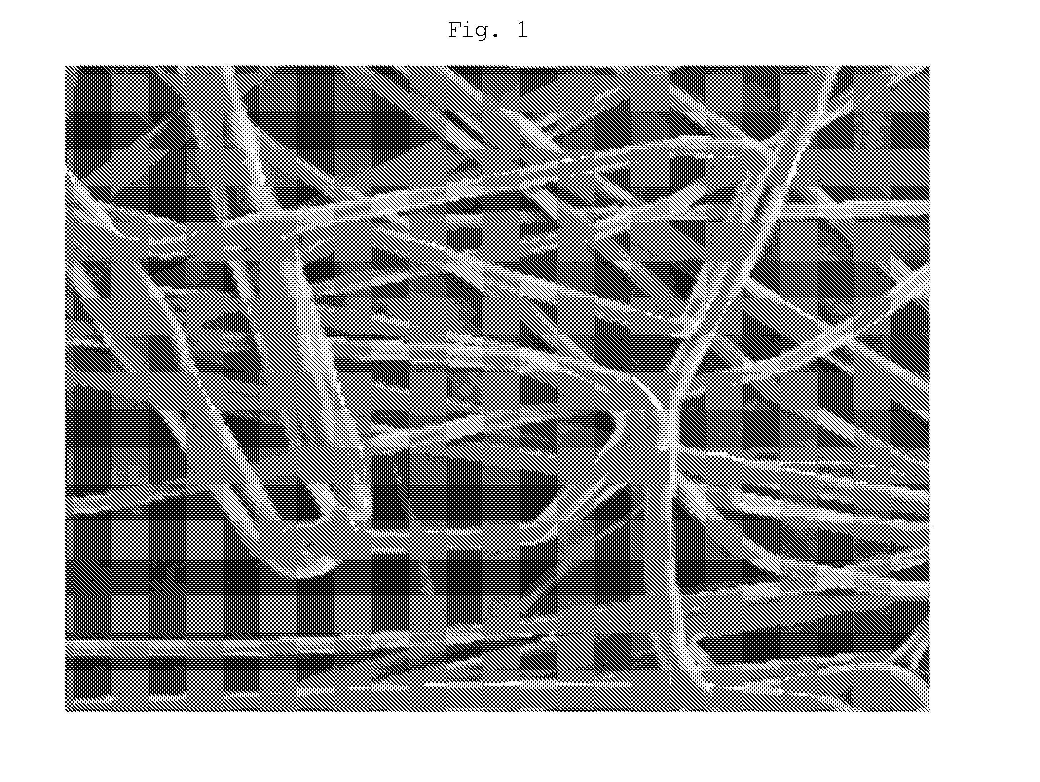
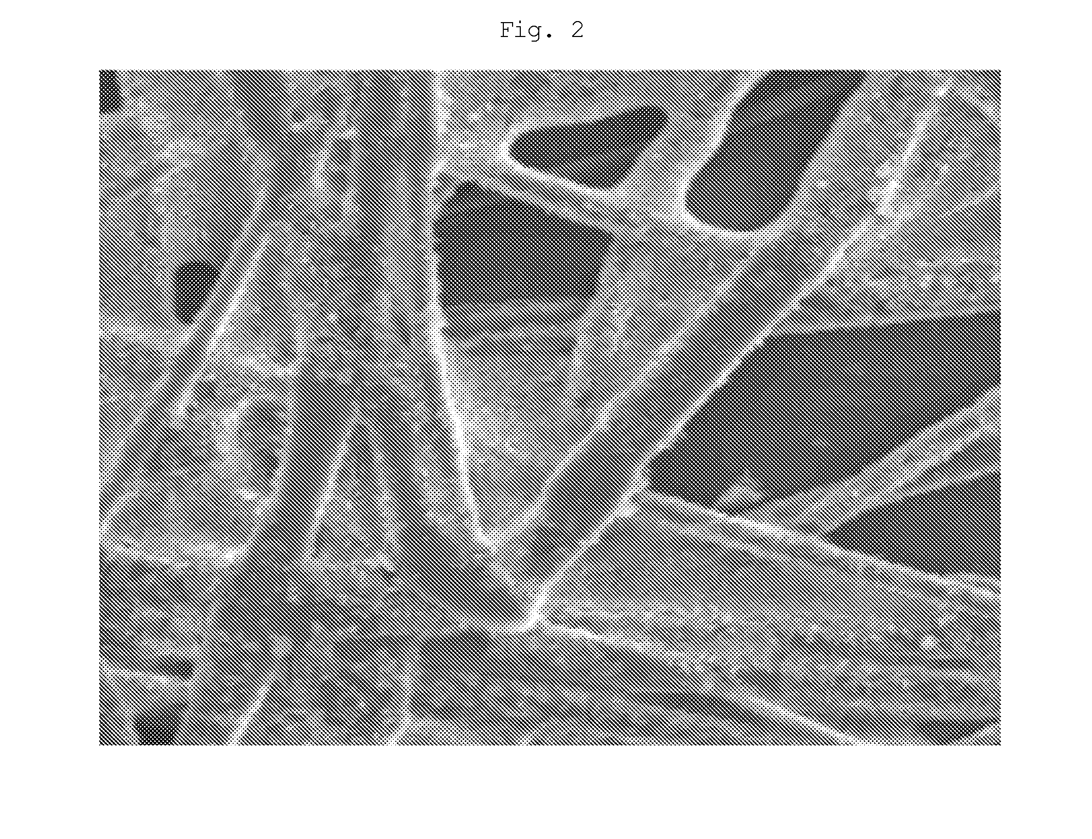
[0088]The PET nonwoven fabric was immersed in the above-prepared mixture solution, and then dried at 80° C. for 6 hours, thereby preparing a ceramic porous substrate comprising the silica nanoparticles bound thereto by the inorganic silane-based binder.

Step 2

Preparation of a Sulfonated Polyarylene Ether Sulfone Copolymer Having a Sulfonation Degree of about 50%

[0089]A 100-ml round-bottom flask equipped with a gas inlet, a thermometer, a Dean-Stark trap, a cooler and a stirrer was purged with nitrogen for several...

example 2

Step 1

Preparation of Ceramic Porous Substrate by Sol-Gel Reaction of TEOS

[0092]TEOS and 0.1N nitric acid (HNO3) were mixed at a weight ratio of 60:40 and treated using an ethyl alcohol solvent in the same manner as Example 1, thereby preparing a mixture solution. Meanwhile, a polyethylene terephthalate (PET) nonwoven fabric having a thickness of 20 μm was selected as a porous polymer base.

[0093]Then, the PET nonwoven fabric was immersed in the above-prepared mixture solution for 5 minutes, and then dried at 80° C. and 120° C. for 4 hours for each temperature, thereby performing a sol-gel reaction of TEOS, thereby preparing a porous substrate having a silicate ceramic layer formed thereon. After the ceramic coating process, the thickness of the substrate was maintained at 20 μm, suggesting that the silicate ceramic layer formed from TEOS was formed in the pores of the nonwoven fabric.

example 3

[0094]The process of Example 1 was repeated, except that silica panoparticles were used as the ceramic layer component in step and mixed with a styrene-butadiene rubber (SBR) binder to prepare a mixture solution, thereby manufacturing a reinforced composite electrolyte membrane.


PUM

PropertyMeasurementUnit
Temperatureaaaaaaaaaa
Fractionaaaaaaaaaa
Pore sizeaaaaaaaaaa

Abstract

The present invention relates to a ceramic porous substrate, a reinforced composite electrolyte membrane using the same, and a membrane-electrode assembly having the same. The ceramic porous substrate comprises: a porous polymer base; and void structures formed on the surface of the porous polymer base by linking the space of the inorganic nanoparticles using a polymer binder or a silane-based inorganic binder. The ceramic porous substrate has improved mechanical properties compared to the porous polymer substrate alone, and the void structures thereof can be controlled in various ways.

Description

TECHNICAL FIELD[0001]The present invention relates to a ceramic porous substrate, a reinforced composite electrolyte membrane using the same, and a membrane-electrode assembly having the same. More specifically, the present invention relates to a substrate which have improved mechanical properties and dimensional stability compared to conventional porous polymer bases, and the void structure of which can be controlled in various ways, and to a reinforced composite electrolyte membrane using the ceramic porous substrate and a membrane-electrode assembly having the reinforced composite electrolyte membrane.BACKGROUND ART[0002]Fuel cells need not to be exchanged or charged, unlike general-purpose cells, and are power-generation cells that convert chemical energy into electrical energy using a fuel such as hydrogen or methanol.[0003]Also, the fuels cells are high-efficiency power generation systems having an energy conversion efficiency of about 60% and their fuel consumption is lower t...

Claims


Application Information

Patent Timeline
IPC IPC(8): H01M8/10B05D5/12B32B18/00B32B5/18B32B27/06
CPCC08J5/22H01M4/9075H01M4/925H01M8/1011C08J2383/02H01M8/1051H01M8/106Y02E60/523H01M8/1039Y02E60/50Y10T428/249967Y10T428/249969Y10T428/24997Y10T442/2139C08J9/00H01M4/86H01M8/10
Inventor HONG, YOUNG TAIKCHOI, JONG HOYOON, KYUNG SEOKLEE, SANG YOUNG
Owner KOREA RES INST OF CHEM TECH
Why Eureka
Try Eureka