Reservoir-buffered mixers and remote valve switching for microfluidic devices

a technology of microfluidic devices and mixers, which is applied in the field of microfluidic devices, can solve the problems of high manufacturing cost, high risk of sample contamination, and loss of sample volume, and achieve the effects of low manufacturing cost, low manufacturing cost, and low cost of disposable components

Inactive Publication Date: 2012-03-29
TRUSTEES OF BOSTON UNIV +1
View PDF5 Cites 44 Cited by
  • Summary
  • Abstract
  • Description
  • Claims
  • Application Information

AI Technical Summary

Benefits of technology

[0019]One advantage of the microfluidic chips comprising flow-rate and / or velocity changing fluid reservoirs is that they have a very low-cost of manufacture due to lack of on-chip valves, and also enables multiple processes using different flow velocities to be performed on a single microfluidic chip. Thus, microfluidic chips comprising and / or velocity changing fluid reservoirs are particularly suited for use as single-use, fully-integrated disposable chips for complete sample processing and analysis in a high throughput manner.
[0020]In particular, in order to achieve a truly low-cost integrated disposable microfluidic chips, in which fluid flow can be regulated in an automated manner, the inventors have minimized the cost of the disposable component by removing all active components from the chip, enabling the chip to have a planar design and to be manufactured using low-cost methods such as injection molding, where a minimal number of assembly steps are required. Additionally, the inventors have used material with dimensional stability at high temperatures (unlike PDMS) and that could be manufactured reproducibly without caustic chemicals (such as hydrofluoric acid which is used to etch glass). In alternative embodiments, one can make the disposable microfluidic chip from any suitable material known by persons of ordinary skill in the art, for example, but not limited to plastics (e.g. acrylic, polycarbonate, etc) and other cheap, durable stable synthetic materials where thermal stability and / or on-chip fluorescence detection is not important.

Problems solved by technology

Even where the microfluidic devices are fluidly connected to each other, the transfer of the sample between the microfluidic devices can increase risk of sample contamination and loss of sample volume.
However, existing microfluidic devices and lab-on-a-chip which comprise multiple modules which require different velocities are highly complicated devices, often comprising on-chip valves, multiple layers and multi-level structures, multiple material types and a number of assembly steps required.
The presence of on-chip valves and multiple layers on microfluidic chips results in very expensive manufacturing costs not suitable for a cheap-disposable lab-on-a-chip system.

Method used


Image

  • Reservoir-buffered mixers and remote valve switching for microfluidic devices
  • Reservoir-buffered mixers and remote valve switching for microfluidic devices
  • Reservoir-buffered mixers and remote valve switching for microfluidic devices

Examples


example 1

[0289]System Design. The lab-on-a-chip system was designed to accomplish the following steps:[0290]1. input 50-400 μL of liquid physiological sample containing a pathogen,[0291]2. mix the sample with a chaotropic buffer to aid in the release of nucleic acids,[0292]3. flow the mixture over the SPE column to further lyse any remaining intact pathogens and bind the nucleic acids on the SPE column,[0293]4. wash the SPE column of proteins and chaotropic agents,[0294]5. dry the SPE column to remove any residual organic solvents,[0295]6. elute the nucleic acids,[0296]7. mix the eluate with PCR master mix,[0297]8. thermally cycle the PCR mixture to amplify the target gene,[0298]9. and detect the resultant amplicon via an end-point fluorescence measurement.

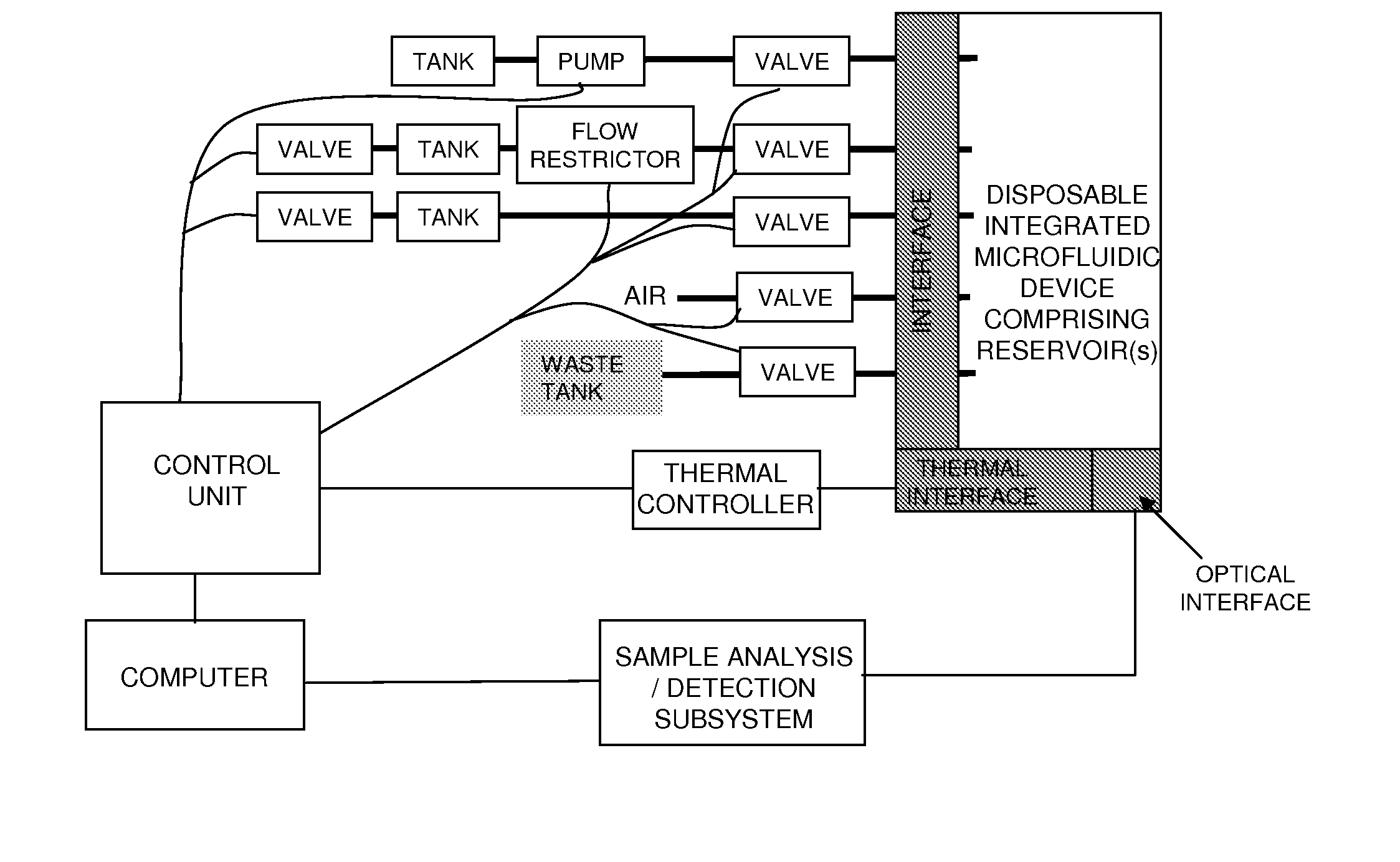
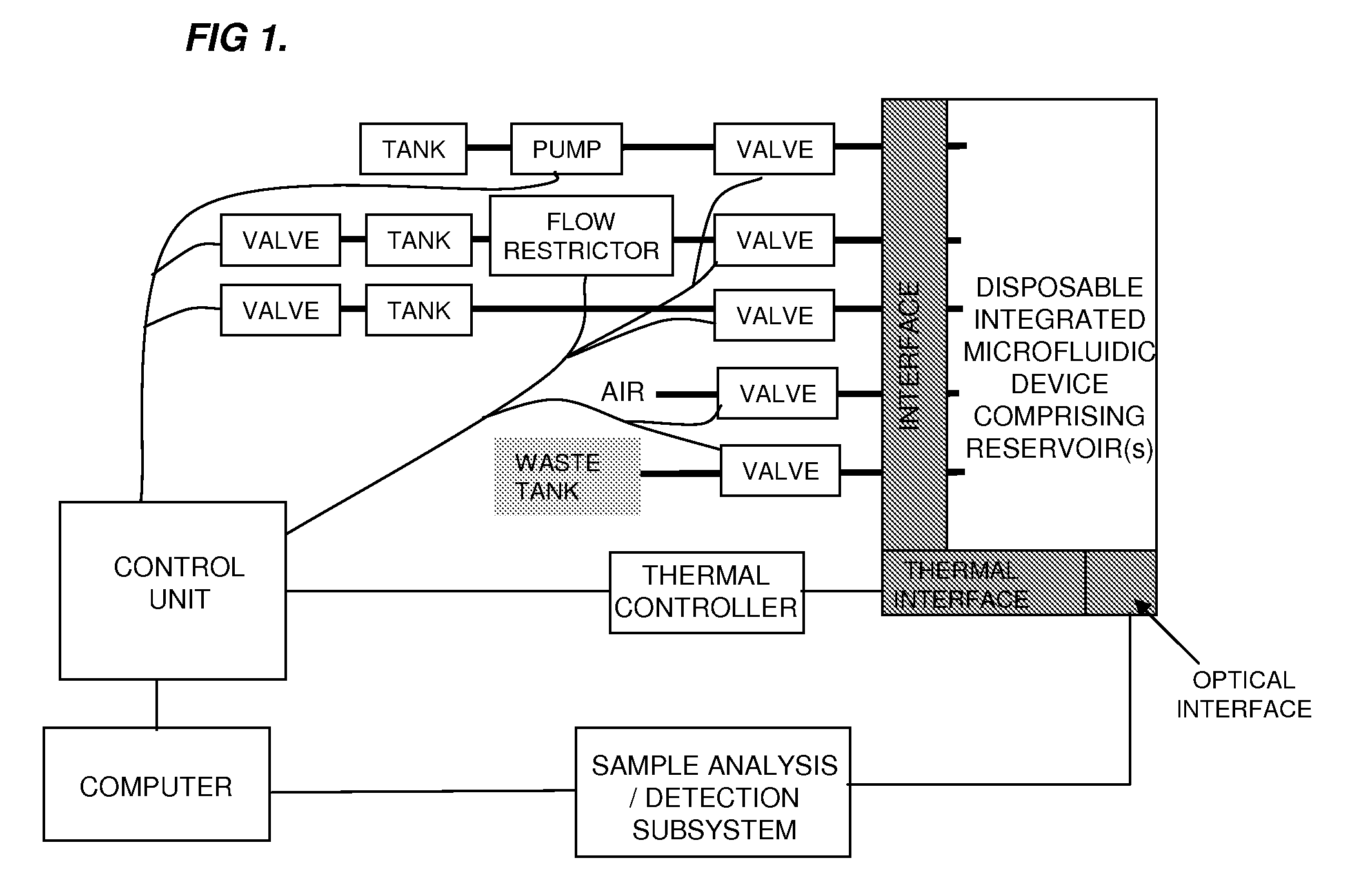
[0299]The system includes two major components: a disposable single-use plastic chip and an instrument which houses all active components to truly make the disposable low cost. To further minimize the cost of the chip, the microfluidic cha...

example 2

[0307]Bacterial detection: To demonstrate the utility of the fully functional chip for detection of bacteria, the inventors conducted a series of experiments with different numbers of input B. subtilis cells (1.25×10⁶, 6.25×10⁶, or 12.5×10⁶ cells). For each chip, the inventors first ran a full-process negative control (water input) followed by the full process with the B. subtilis cells. The inventors present the optical detection data as the difference between the signal with B. subtilis and the same chip's negative control in FIG. 13A. After the on-chip detection was completed, the inventors collected the contents of the detection well and analyzed the sample by gel electrophoresis to confirm the presence of the target amplicon (FIG. 13B).

[0308]All three concentrations of B. subtilis were detected above the negative signal demonstrating that the system can successfully lyse the bacteria and isolate the nucleic acids, PCR amplify the target, and detect the presence of the amplicon ...

example 3

[0309]The main contributions described in this article are the design, implementation and demonstration of an end-to-end lab-on-a-chip system for the detection of bacteria that is truly low cost to manufacture. The field of microfluidic total analysis systems promises low-cost systems by miniaturizing and automating traditionally labor and reagent intensive processes. However, many of the innovations are complicated and expensive to manufacture and / or made of materials that are not robust for commercial application. To minimize the complexity and cost of the disposable component, the inventors designed a completely passive chip in a planar format that can be injection molded. The inventors have developed the injection molding process for this chip and will present the manufacturing methodology elsewhere. To achieve the full integration and automation of the laboratory steps required (sample and reagent introduction, mixing, nucleic acid isolation, PCR and optical detection), the inv...


PUM

PropertyMeasurementUnit
concentrationsaaaaaaaaaa
flow rateaaaaaaaaaa
flow rateaaaaaaaaaa

Abstract

The present invention relates generally to the control of fluid flow rate and direction on a microfluidic device. In particular, the present invention provides an integrated valveless microfluidic device, where directional fluid control is controlled using off-chip remote valve switching and fluid flow rate changes are controlled using on-chip flow-rate changing fluid reservoirs. The present invention provides methods and systems for directional fluid control and control of fluid flow rate in an integrated microfluidic device which enables processes with different flow rates to be performed on one device without the need of on-chip valves.

Description

CROSS REFERENCE TO RELATED APPLICATIONS[0001]This application claims priority under 35 U.S.C. 119(e) of U.S. Provisional Patent Application Ser. No. 61 / 164,756 filed Mar. 30, 2009, the contents of which are incorporated herein by reference in their entirety.FIELD OF THE INVENTION[0002]The present invention generally relates to the field of microfluidic devices, and in particular integrated microfluidic devices and the control of the movement of fluid within microfluidic devices. In particular, the present invention relates to methods, devices, systems and instruments for directional fluid control and rate of fluid control, using remote valve switching devices and systems and reservoir buffered devices and systems respectively.BACKGROUND OF THE INVENTION[0003]Currently, the majority of infection diagnoses, e.g. bacterial, parasites, fungi, viruses are conducted via cultures2 or immunoassays or PCR (e.g. viruses), which can take many hours to days. Thus, physicians will typically pres...

Claims


Application Information

Patent Timeline
Patent Type & Authority Applications(United States)
IPC IPC(8): C12M1/40G01N21/75B01L3/00
CPCB01L3/502715G01N2035/00237B01L3/502746B01L7/52B01L2200/10B01L2200/143B01L2200/146B01L2200/147B01L2300/0816B01L2300/0861B01L2300/0883B01L2300/1822B01L2300/1827B01L2300/1838B01L2400/06B01L2400/0688B01L2400/082B01L2400/084G01N35/1097B01L3/502738
Inventor SHARON, ANDRECHARGIN, DAVID A.MIRSKY, PAULSAUER-BUDGE, ALEXIS
Owner TRUSTEES OF BOSTON UNIV
Why Eureka
Try Eureka