Photovoltaic power conditioning units

Active Publication Date: 2012-04-05
TESLA INC
View PDF7 Cites 189 Cited by
  • Summary
  • Abstract
  • Description
  • Claims
  • Application Information

AI Technical Summary

Benefits of technology

[0009]The input power converters may have outputs connected to the dc bus either in parallel or in series. When the outputs are connected in series the effective shading of a sub-string is to reduce the voltage on the dc bus and thus in the circumstances the bypass controller (or another controller of the power conditioning unit) may control the remaining, unshaded input converters to increase that output voltage to compensate. This may be achieved, for example, by changing the operating frequency of a resonant converter such as an LLC converter to pull the converter off resonance and increase the voltage gain by a factor of 50% (this otherwise being determined by the terms ratio of the transformer). Alter

Problems solved by technology

A shaded cell of a PV panel becomes a load and power generated in other solar cells of the panel may be dissipated in the shaded cell, creating a local hotspot and resulting in long term degradation and premature failure of the panel.
This can be addressed

Method used


Image

  • Photovoltaic power conditioning units
  • Photovoltaic power conditioning units
  • Photovoltaic power conditioning units

Examples


first embodiment

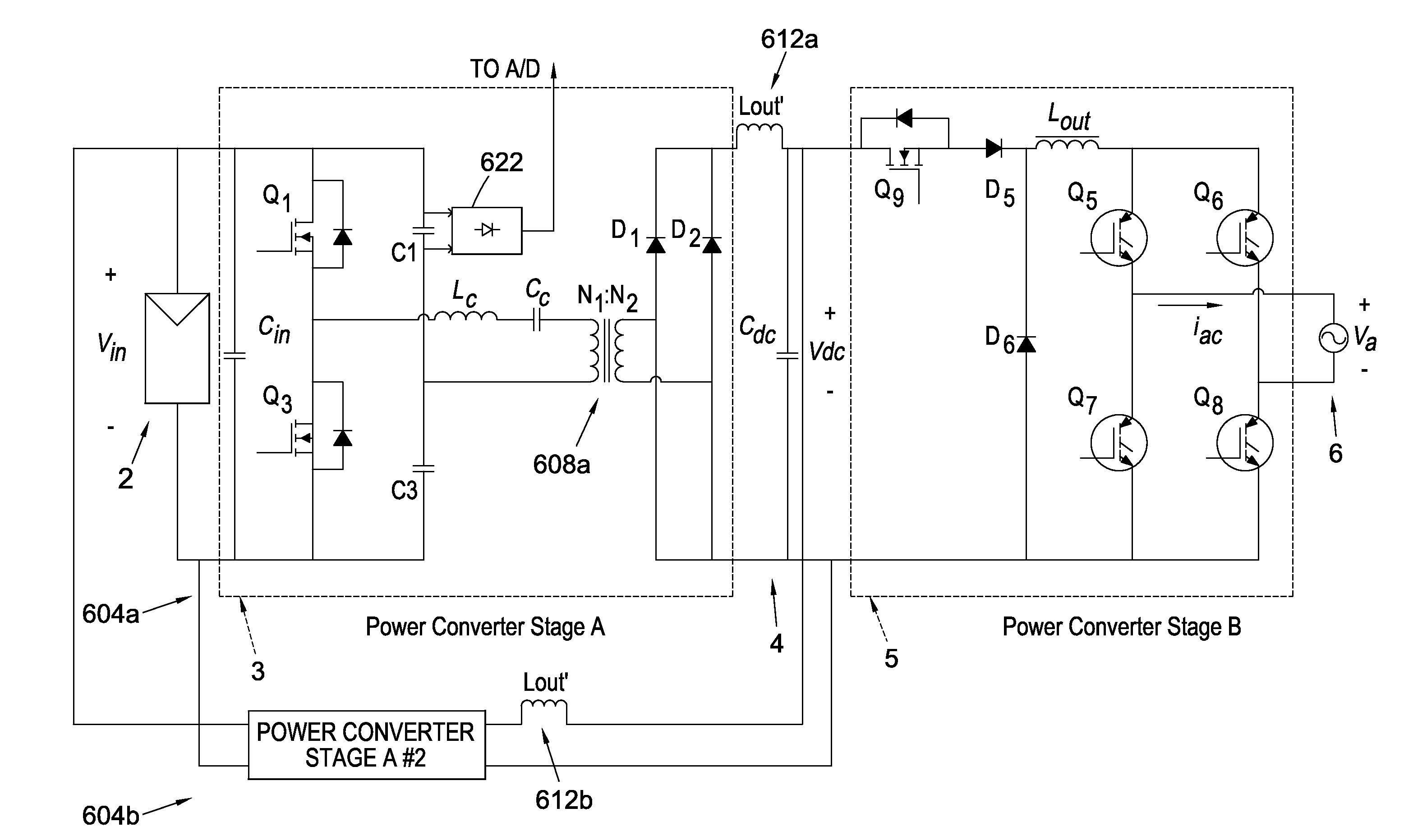
[0067]Thus referring now to FIG. 4a, this shows a power conditioning unit 600 according to an aspect of the invention. In the architecture of FIG. 4 a photovoltaic module 602 provides a dc power source for first and second dc-to-dc power conversion stages 604a, b, in this example each comprising an LLC resonant converter. Thus each of power conversion stages 604 comprises a dc-to-ac (switching) converter stage 606a, b to convert dc from module 602 to ac for a respective transformer 608a, b. The secondary side of transformers 608a, b are coupled to respective rectifying circuits 610a, b, which in turn provide a dc output to a respective series-coupled output inductor 612a, b. Each of output inductors 612a, b is coupled to a dc link 614 of the power conditioning unit, to which is also coupled a dc link capacitor 616. A dc-to-ac converter 618 has a dc input from a dc link and provides an ac output 620, for example to an ac grid mains supply.

[0068]A microcontroller 622 provides switchin...

second embodiment

[0071]Referring now to FIG. 4c, this shows the power conditioning unit 650 similar to that of FIG. 4a but with an improved arrangement of output inductors. More particularly the output inductors 612 of the FIG. 4a are incorporated into respective transformers 652a, b of the front end dc-to-dc converter stages to facilitate load sharing between the conversion stages.

[0072]FIG. 4d illustrates example waveforms of multiphase interleaving of the switching of the converters 604a,b (in the Figure the waveforms illustrate example data control signals of the switches in stages 606a, b of the converters). To reduce ripple on the input capacitor the switching is preferably 180° out of phase between the two converters. However in embodiments the rectification circuits 610a,b of the power converters may be shared (not shown), i.e. so that a common set of rectifiers / rectification circuits is employed for both converters. In this case the interleaving between the dc-to-ac conversion portions of t...


PUM


Abstract

We describe a photovoltaic (PV) panel system comprising a PV panel with multiple sub-strings of connected solar cells in combination with a power conditioning unit (microinverter). The power conditioning unit comprises a set of input power converters, one connected to each sub-string, and a common output power conversion stage, to provide power to an ac mains power supply output. Integration of the micro-inverter into the solar PV module in this way provides many advantages, including greater efficiency and reliability. Additionally, embodiments of the invention avoid the need for bypass diodes, a component with a high failure rate in PV panels, providing lower power loss and higher reliability.

Description

FIELD OF THE INVENTION[0001]This invention relates to system architectures, circuits and techniques for photovoltaic (PV) power conditioning units. Embodiments of the invention are particularly useful for addressing problems associated with partial shading of a PV panel.BACKGROUND TO THE INVENTION[0002]In a photovoltaic module (panel) the panel is made up of series-connected mono crystalline or polycrystalline solar cells, each having a forward voltage of around 0.6V, that is a forward diode drop. These are then series connected to form sub-strings, nominally of around 10V for a 60 cell module, and 12V for a 72 cell module. Under certain circumstances the solar PV modules can become partly shaded, for example from fallen leafs or from part of a building and no longer generate current or voltage. It is desirable to be able to improve the power harvest from a PV panel under such circumstances, in particular whilst protecting the PV panel from damage.[0003]Background prior art can be f...

Claims


Application Information

Patent Timeline
IPC IPC(8): H02M5/458
CPCH02J3/383H02M3/285H02M7/46Y02E10/563H02M7/4807H02J2300/24H02J3/381Y02E10/56H02J2300/26H02J3/40G05F1/67H02J1/12H02J3/38H02J3/46H02M5/458
Inventor GARRITY, PAULMUMTAZ, ASIM
Owner TESLA INC
Why Eureka
Try Eureka