
Nozzle For A Thermal Spray Gun And Method Of Thermal Spraying

a technology of thermal spraying and nozzles, which is applied in the direction of liquid/solution decomposition chemical coatings, solid/suspension decomposition chemical coatings, pressure inorganic powder coatings, etc., can solve the problems of reducing spraying accuracy, reducing deposition efficiency, and reducing spraying accuracy, so as to reduce the loss of energy/temperature of powder particles, reduce the loss of energy, and increase the stability of the jet

Active Publication Date: 2012-04-05
MONITOR COATINGS
View PDF11 Cites 7 Cited by
  • Summary
  • Abstract
  • Description
  • Claims
  • Application Information

AI Technical Summary

Benefits of technology

[0016]By creating a divergence in the stream of combustion gases, which then recombine into a single stream, a number of advantages are provided. Firstly, the nozzle of the present invention generates a more stable supersonic jet which reaches a higher axial velocity (around 2 mach) and is maintained for longer than in devices of the prior art under the same conditions of oxygen / fuel mixture and mass flow rate. The device of the present invention also reduces the trailing shock waves (diamond shock waves seen in the prior art jet) thereby reducing the loss of energy / temperature of the powder particles. This results in a single expansion of the flow, just after the tip of the diverging means, reducing the loss of energy. As a result, of the increased stability of the jet, the barrel portion of the nozzle is not necessary and can be eliminated. The overall length of the nozzle is therefore reduced allowing spraying of previously inaccessible surfaces, for example, internal surfaces of components.
[0017]Furthermore, because a divergence is created in the combustion gas stream, either producing two or more linear gas streams with the diverging means between them or an annular stream with the diverging means at the centre, the coating material can be introduced within the gap or divergence created in the stream by the divergence means. As a result, the coating material is never in contact with the fuel and oxygen mixture and is only in contact with the combusted gases once combustion is complete. As a result, the risk of oxidation of the coating material is reduced. This risk of oxidation is further reduced by the stability of the flame which increases the likelihood of oxygen from the surrounding air mixing with the stream of combusted gases and coating material.
[0018]Another factor allowing the elimination of the barrel is that the introduction of the powder immediately downstream of the diverging means results in the coating material being introduced into relatively slow moving but hot portion of the gas stream. As a result, in-flight time that the particle of coating material experiences, that is the time from introduction into the gas stream to deposition on the coated product, increases ensuring that each particle is properly heated. In some nozzles of the prior art, where particles are introduced into a fast flowing gas stream, there is little time for the particles to become sufficiently heated and the barrel is used to maintain the heat in the gas stream, before it begins to mix with the ambient air, to ensure sufficient heating of the particles.
[0021]By introducing the coating material on the downstream side of the diverging means, the advantage is provided that the coating particles do not pass through the nozzle and therefore do not come into contact with any part of the nozzle, such as a barrel. As a result, the heated particles do not damage the nozzle thereby extending the lifespan of a nozzle. Furthermore, because particles of coating material are being introduced into the middle of a stable stream of combustion gases the particles do not suffer much radial deflection meaning that they are more likely to remain within the gas stream. This in turn means that smaller particles of coating material (<10 μm) can be used for coating. Furthermore, the introduction of coating material into the middle of the stable and converging jet reduces waste from larger particle moving radially and missing their target.

Problems solved by technology

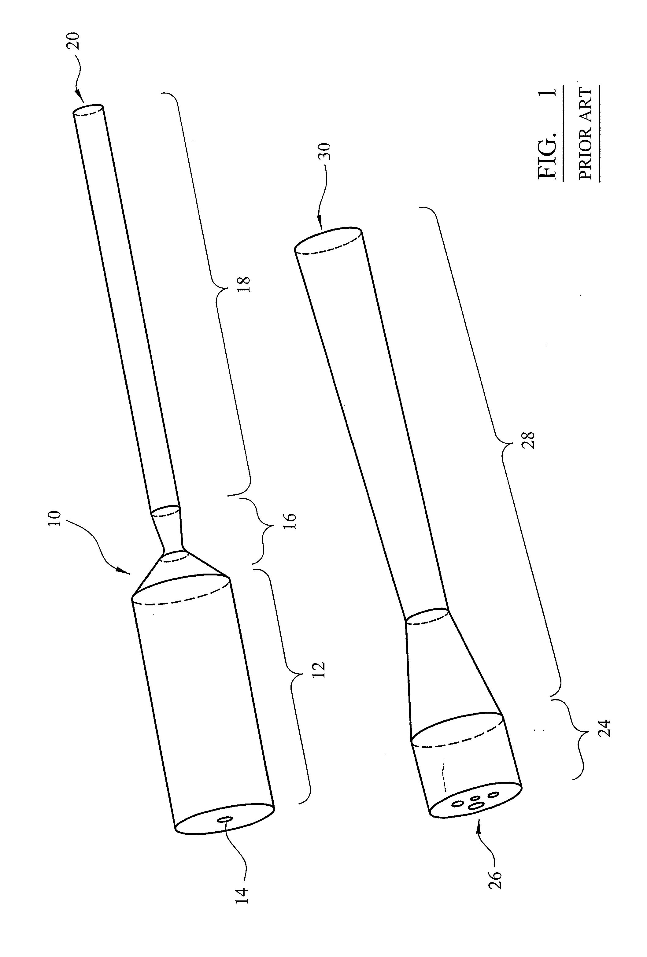
As a result, injection of the powder into the centre of the combustion chamber is not appropriate for this material and generally for non-ceramic materials and therefore the powdered material must be injected into the stream of supersonic gases.
However, this gives the particles momentum in a radial direction making them likely to leave the gas stream before impacting on the article to be coated.
In practice, particle spreading reduces the spraying accuracy and decreases deposition efficiency because particle impact is not normal to the surface that is being coated.
Furthermore, injection of the powder into the nozzle results in damage to the nozzle, in particular erosion of the barrel's wall, and as a result the nozzle, or at least the barrel section, typically must be replaced every ten hours of operation.
The shock wave diamonds result in a loss of temperature and expansion on exiting the barrel increases the temperature loss.
This long barrel, typically 350 mm, limits the applications to which the thermal sprayer can be applied, for example, internal surfaces of even quite large components are impossible to spray.
Small particles, below 10 μm, cannot practically be used because such small powdered material disperses in the gas field and consequently rebound from or never reach the article being sprayed.
As a result, the small particles never reach the flow centre line and therefore cannot benefit from the high velocity / temperature flow regions.

Method used


Image

  • Nozzle For A Thermal Spray Gun And Method Of Thermal Spraying
  • Nozzle For A Thermal Spray Gun And Method Of Thermal Spraying
  • Nozzle For A Thermal Spray Gun And Method Of Thermal Spraying

Examples


Embodiment Construction

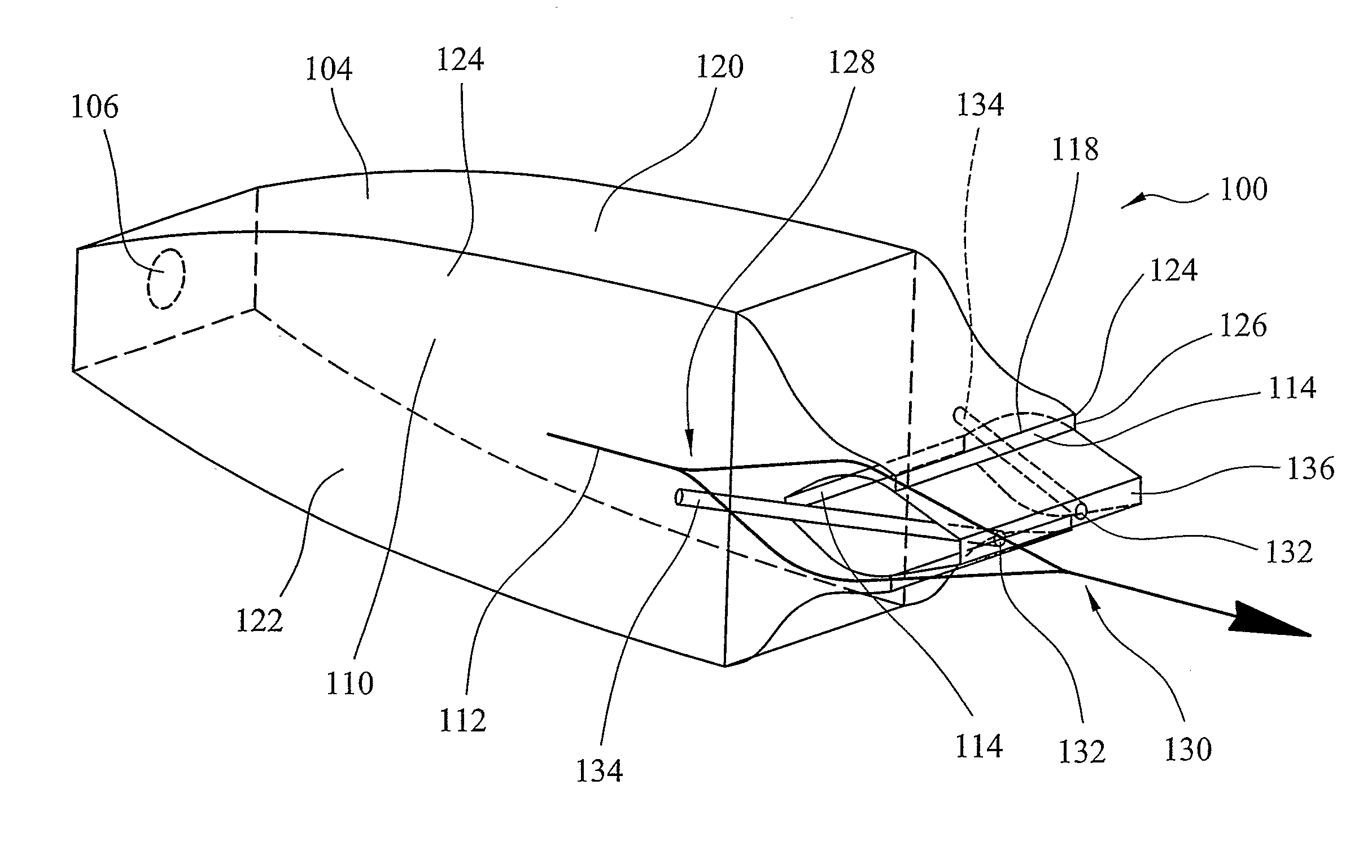
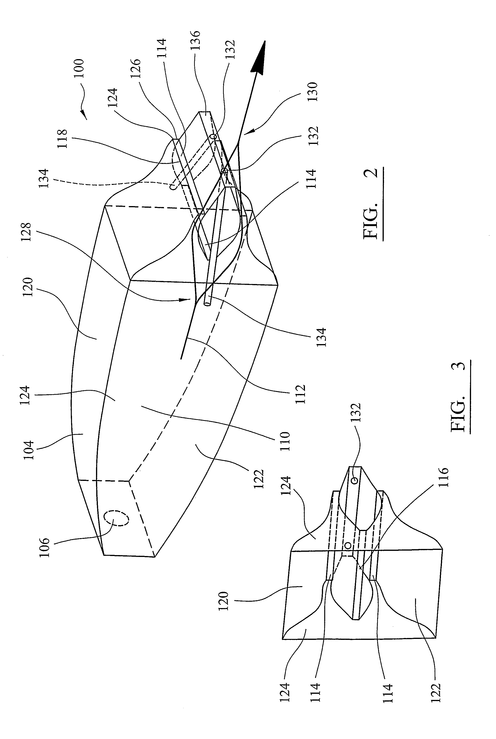
[0051]Referring to FIGS. 2 to 5, a nozzle 100 for a thermal spray gun 102 has a combustion chamber 104. An inlet 106 introduces fuel into the combustion chamber from a fuel supply pipe 108. The fuel is burnt in a combustion zone 110 and a stream of combustion gases that leave the combustion chamber 104 through exhausts 114. The nozzle 100 also includes diverging means, in the form of aerospike 116, that is located partially within the combustion chamber. The aerospike 116, in combination with edges 118 of the curved top and bottom walls 120 and 122 and side walls 124 with edge 126, form exhausts 114. It should be noted that the side wall, opposing the side wall 124 shown in FIG. 2, is not illustrated in either FIG. 2 or FIG. 5, but is partially present in FIG. 3.

[0052]The presence of the aerospike 116 between exhausts 114 causes the stream 112 of combustion gases to diverge, as indicated at 128, and to converge as indicated at 130.

[0053]The nozzle 100 also has coating material inlet...


PUM

PropertyMeasurementUnit
flame temperatureaaaaaaaaaa
temperatureaaaaaaaaaa
velocityaaaaaaaaaa

Abstract

A nozzle for a thermal spray gun and a method of thermal spraying are disclosed. The nozzle has a combustion chamber within which fuel is burned to produce a stream of combustion gases. The streams of heated gases exit through a pair of linear exhausts which are located on either side of an aerospike. The streams converge outside the nozzle and powdered coating material is introduced into the converging streams immediately downstream of the aerospike. The coating material is heated and accelerated before impacting on a substrate to be coated.

Description

CROSS-REFERENCE TO RELATED APPLICATIONS[0001]This application is a National Stage entry from PCT Patent Application No. PCT / GB2010 / 050482 filed on 23 Mar. 2010, which claims priority to British Patent Application GB0904948.7 filed on 23 Mar. 2009. The contents of each of these applications is hereby incorporated by reference in its entirety.BACKGROUND OF THE INVENTION[0002]1. Field of the Invention[0003]The present invention relates to a nozzle for a thermal spray gun and to a method of thermal spraying and relates particularly, but not exclusively, to a nozzle for a high velocity oxygen fuel (HVOF) thermal spray gun and method of HVOF thermal spraying.[0004]2. Description of the Related Art[0005]Techniques of thermal spraying, where a coating of heated or melted material is sprayed onto a surface, are well known. One such technique is high velocity oxygen fuel thermal spraying in which a powdered material, for example Tungsten Carbide Cobalt (WC—Co), is fed into a combustion gas fl...

Claims


Application Information

Patent Timeline
Patent Type & Authority Applications(United States)
IPC IPC(8): B05B1/00B05D1/02B05B7/02
CPCB05B7/205C23C24/04C23C4/124C23C4/129B05B7/1486B05B7/20
Inventor ALLCOCK, BRYANGU, SAIKAMNIS, SPYROS
Owner MONITOR COATINGS
Learn More