Cell Analysis On Microfluidic Chips

a microfluidic chip and cell technology, applied in combinational chemistry, biochemistry apparatus, chemical libraries, etc., can solve the problems of high labor intensity and time-consuming, human observer still needs to manually perform, and most only perform well on noise-free precision-focused images from expensive optical setups

Inactive Publication Date: 2012-04-05
THE GOVERNORS OF THE UNIV OF ALBERTA
View PDF1 Cites 11 Cited by
  • Summary
  • Abstract
  • Description
  • Claims
  • Application Information

AI Technical Summary

Benefits of technology

[0032]In another aspect, the fluid is a buffer suitable for maintaining the size and shape of the individual cells making up the population of cells of interest. In a further aspect, the fluid i

Problems solved by technology

One drawback of the current FISH analysis protocols is that a human observer is still required to manually assess the outcome of the tests (Theodosiou, Z. et al., Cytometry A, 71A:439-450 (2007); Lerner, B. et al., Ieee-Acm Transactions On Computational Biology and Bioinformatics, 4:204-215 (2007)).
While computer systems have been designed to address these difficulties, most only perform well on noise-free precision-focused images from expensive optical setups.
Since some of the therapies have secondary effects that greatly compromise quality of life, it is necessary to determine the appropriate therapeutic approach for each patient.
However, the complexity and numerous protocol steps involved in a typical interphase FISH analysis

Method used


Image

  • Cell Analysis On Microfluidic Chips
  • Cell Analysis On Microfluidic Chips
  • Cell Analysis On Microfluidic Chips

Examples


example 1

Cell Preparation and Immobilization

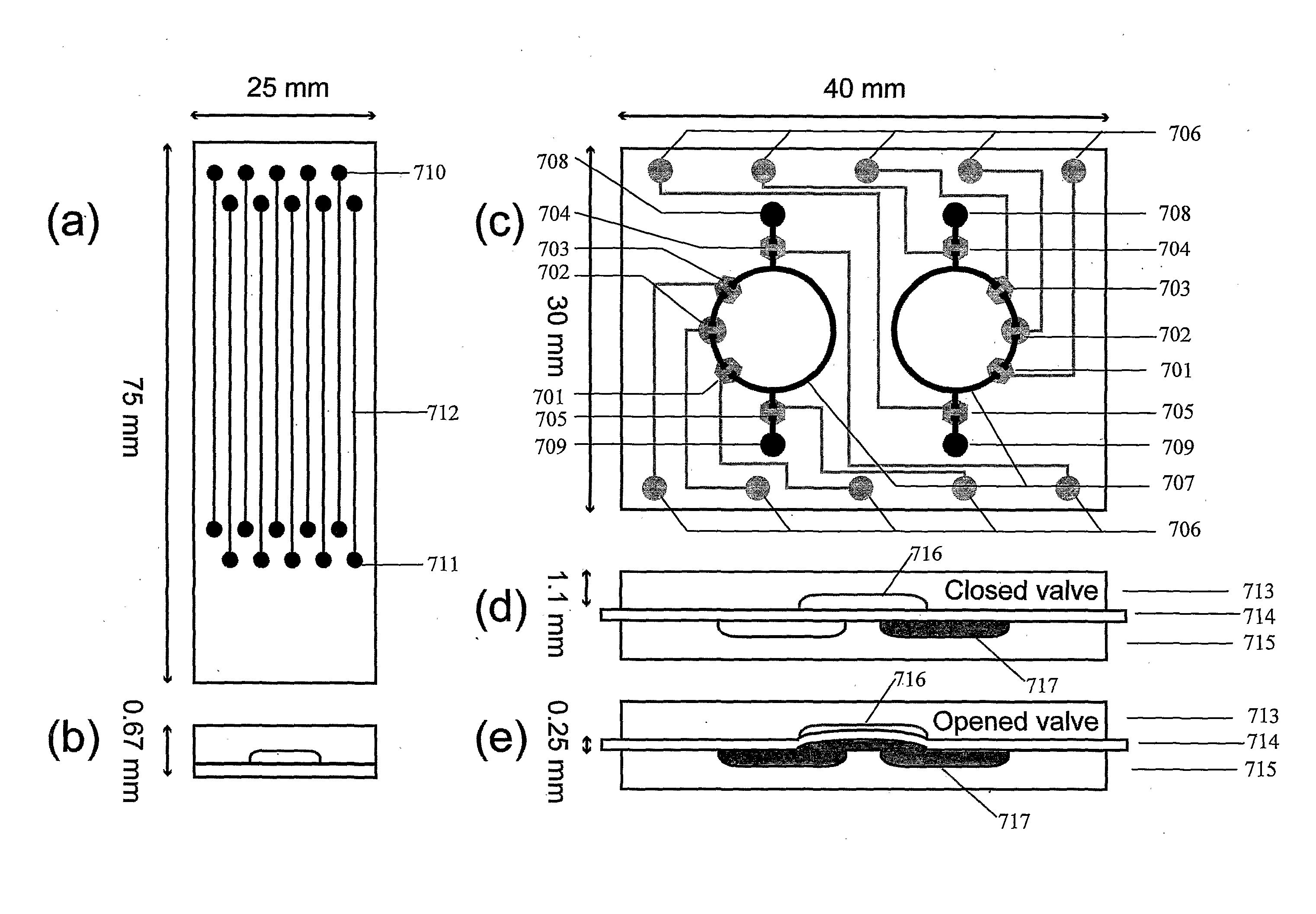
[0146]Before FISH could be implemented within a microfluidic platform, it was necessary to develop a method for immobilizing cells within channels. From an initial concentration of ˜10 million cells per millilitre, ˜15,000 cells suspended in 1×PBS were added to each sample access port / well (1.5 μL). Capillary force moved the cells (in solution) into the microchannel 712, coating the surfaces over entire length the channel. Any remaining cells in the wells were removed, with a pipette. The microchips were then heated to an optimal temperature of 85° C. for 10 minutes. The remaining cell solution in the channels were removed with a filtered vacuum line (20 in·Hg) applied to port / well 711, or optionally and in the alternative 710. After temperature immobilization, approximately 70% of the cells remained adhered to the channel walls, with almost 90% of the cells immobilized on the bottom of the channel (etched surface). The temperature-induced immobili...

example 2

Circulating Microchip

[0148]A circulating microchip was designed such that the probe could be recirculated over the immobilized cells, facilitating more rapid and efficient hybridization. This required a microfluidic network and a pneumatic pumping and valving system, as illustrated by the combined mask layouts shown in FIG. 7(c). The circulating chip is built with three layers: a rigid layer 715 with fluid channels, a flexible middle layer 714 that acts as a controllable membrane, and an adjacent layer 713 with control channels and chambers for actuating the valves and pumps. Layer 715 consists of two discontinuous circular fluid channels 707 (nominal dimensions are 40 μm×580 μm with a radius of 5 mm) each with two wells 708, 709 (each containing ca. 1.5 μL) in 1.1 mm thick borofloat glass (Precision Glass and Optics, Santa Ana, Calif.). Middle layer 714 was a 0.254 mm thin sheet of PDMS (HT-6135, Bisco Silicons, Elk Grove, Ill., USA). Layer 713 was fabricated on 1.1 mm borofloat gl...

example 3

Hybridization within the Microchip

[0150]Using the chip design of FIG. 7(a), a probe solution described herein was added to the sample wells 710 of the chip and vacuum applied to the opposite well 711 to pull the viscous probe solution into the channel 712. The total volume of probe used was 1 μL (approximately 1 / 10th that used on conventional microscope slides). The wells 710, 711 were then blocked with rubber cement to prevent evaporation. Next, a set of thermal sequences permitted controlled denaturation of the chromosomal and probe DNA. The program sequence was as follows: a) 37° C. for five minutes; b) 75° C. for five minutes; c) hold at 37° C. For diffusion-based experiments, the probe was left in the channel to hybridize for the time duration desired, which ranged from 1-14 hours. Following hybridization the channel seals over wells / ports 710, 711 were removed and 20 μL of 0.4×SSC at 70° C. was flushed through the channels 712. The channels were then emptied, and filled with 2...


PUM

PropertyMeasurementUnit
Temperatureaaaaaaaaaa
Lengthaaaaaaaaaa

Abstract

The present invention provides for a method of implementing fluorescent in situ hybridization (FISH) or other cellular analysis processes using intact cells within a microfluidic, chip-based, apparatus. The invention further provides for a method of cellular immobilization within a microfluidic device. Also provided is a method for automated analysis of FISH or other cellular analysis using discrete colormetric probes.

Description

RELATED APPLICATION[0001]This application claims the benefit of U.S. Provisional Application Ser. No. 60 / 844,643, filed Sep. 15, 2006, filed under 35 U.S.C. 119(e). The entire disclosure of the prior applications are hereby incorporated by reference.FIELD OF THE INVENTION[0002]The present invention pertains to the field of cellular analysis.BACKGROUND OF THE INVENTION[0003]All of the publications, patents and patent applications cited within this application are herein incorporated by reference in their entirety to the same extent as if the disclosure of each individual publication, patent application or patent was specifically and individually indicated to be incorporated by reference in its entirety.[0004]Fluorescent In Situ Hybridization (FISH) is a safe, stable clinical test for abnormal genetic mutations in human cells. One particular use of FISH is the detection of anomalous chromosome structures in patients with cancers of the blood and immune systems (hematopoietic disorders...

Claims


Application Information

Patent Timeline
IPC IPC(8): C12Q1/68G06K9/00C12M1/34
CPCB01J2219/00605B01J2219/00689B01J2219/00702B01J2219/00743C12Q1/6841G01N21/6458C40B60/12C12Q2565/629C12Q2563/107
Inventor PILARSKI, LINDADEBES-MARUN, CARINAPILARSKI, PATRICKBACKHOUSE, CHRISTOPHERSIEBEN, VINCENTKAIGALA, GOVIND
Owner THE GOVERNORS OF THE UNIV OF ALBERTA
Why Eureka
Try Eureka