Pet imaging of fibrogenesis

a fibrogenesis and pet imaging technology, applied in the field of peptide compounds, can solve the problems of unsuitable in vivo liver imaging optimal, and achieve the effect of most efficacious treatmen

Inactive Publication Date: 2012-04-26
GE HEALTHCARE LTD
View PDF4 Cites 1 Cited by
  • Summary
  • Abstract
  • Description
  • Claims
  • Application Information

AI Technical Summary

Benefits of technology

[0003]The in vivo imaging technique positron emission tomography (PET) provides excellent sensitivity and resolution, so that even relatively small changes in a lesion can be observed over time. A preferred positron-emitting nuclide for use in PET is 18F, which has a half-life of approximately 110 minutes, decays 97% by positron emission, and has a maximum energy of 0.69 MeV. An 18F-labelled peptide that targets a biomarker representative of a particular disease state can be used in the detection and characterisation of that disease state.
[0007]Currently-used approaches for the detection of liver fibrosis have some notable disadvantages. Liver biopsy analysed histologically for the pattern of collagen deposition is considered the gold standard for assessing liver disease stage and liver fibrosis. However, the procedure is associated with some morbidity, occasional mortality, high costs, sampling errors, and high inter-observer variability among hepatopathologists in categorising the degree of fibrosis. Errors in stage diagnosis can be made because biopsy sampling of liver results in only 1 / 50,000th of the liver being assessed. Furthermore, in order to monitor disease progression in a timely manner, it is recommended that repeat biopsies are carried out every 3-5 years. Less invasive strategies are available, such as blood tests, but current blood tests for detecting liver fibrosis are of limited value clinically as they cannot be used for assessing the degree of fibrosis or for discriminating fibrosis from cirrhosis. At present, there is no method that can distinguish NAFLD from NASH, or satisfactorily quantify and characterise fibrosis in NASH. There is therefore no means by which liver fibrosis can effectively be characterised and monitored via a non-invasive procedure. This has a negative impact on the provision of early therapeutic intervention, which may slow or halt liver fibrosis. An in vivo imaging method capable of detecting the early stages of fibrosis would be useful in the clinical management of the NAFLD disease process.

Problems solved by technology

However, in vivo data that has been presented more recently demonstrates that 18F-labelled RGD peptides have characteristics rendering them unsuitable for optimum in vivo imaging of the liver.

Method used


Image

  • Pet imaging of fibrogenesis
  • Pet imaging of fibrogenesis
  • Pet imaging of fibrogenesis

Examples


example 1

Binding to Membranes Prepared from EA-Hy926 Cells

[0048]The inhibition constant was measured using a previously-described membrane binding assay (Indrevoll et al, Bioorg & Med Chem Lett, 2006, 16, 6190-6193).

In brief, membranes from the human endothelial adenocarcinoma cell line EA-Hy926 were prepared and the Kd calculated for the purified membrane fraction. A competitive binding assay was then established to measure inhibition constants. 125I-echistatin (GE Healthcare; Code IM304) was used as the labelled ligand and cold echistatin as a reference standard.

A total of sixteen dilutions of cold test compound (either cold echistatin or cold PET tracer) were prepared and mixed with a combination of 125I-echistatin and membrane prior to incubation for 1 hour at 37° C. Following several washes, the bound material was harvested on a filter using a Skatron micro harvester. The filterspots were finally excised and counted in a Packard γ-counter.

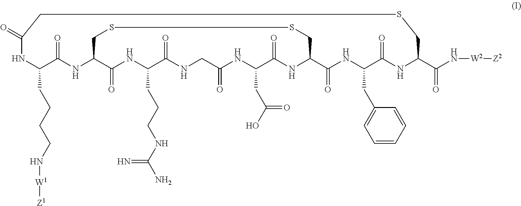
PET tracer 1 (prepared by the method described b...

example 2

Bile Duct Ligation (BDL) and Sham Animals

2(i) Animal Model Set-Up

[0049]Outbred male Sprague Dawley rats (180-200 g; Charles River) were used in all bile duct ligation (BDL) and sham studies. After 6 days acclimatization rats were divided into 2 groups (BDL group and sham group).

For the BDL animals, the abdomen was shaved and swabbed with betadine solution followed by 5 mg / kg carprofen subcutaneously (s.c.) and 5 mg / kg bupronorphine s.c. and under Isoflurane anaesthesia a mid-line laparotomy was performed and the common bile duct located. Bile duct was double ligated, the first ligation made between the junction of the hepatic ducts and the second above the entrance of the pancreatic ducts.

The second group (sham animals) abdomen was shaved and swabbed with betadine solution followed by 5 mg / kg carprofen s.c. and 5 mg / kg bupronorphine s.c. Animals underwent sham surgery where bile duct was manipulated and a suture passed under the bile duct.

Before closing 2-3 ml saline was administere...

example 3

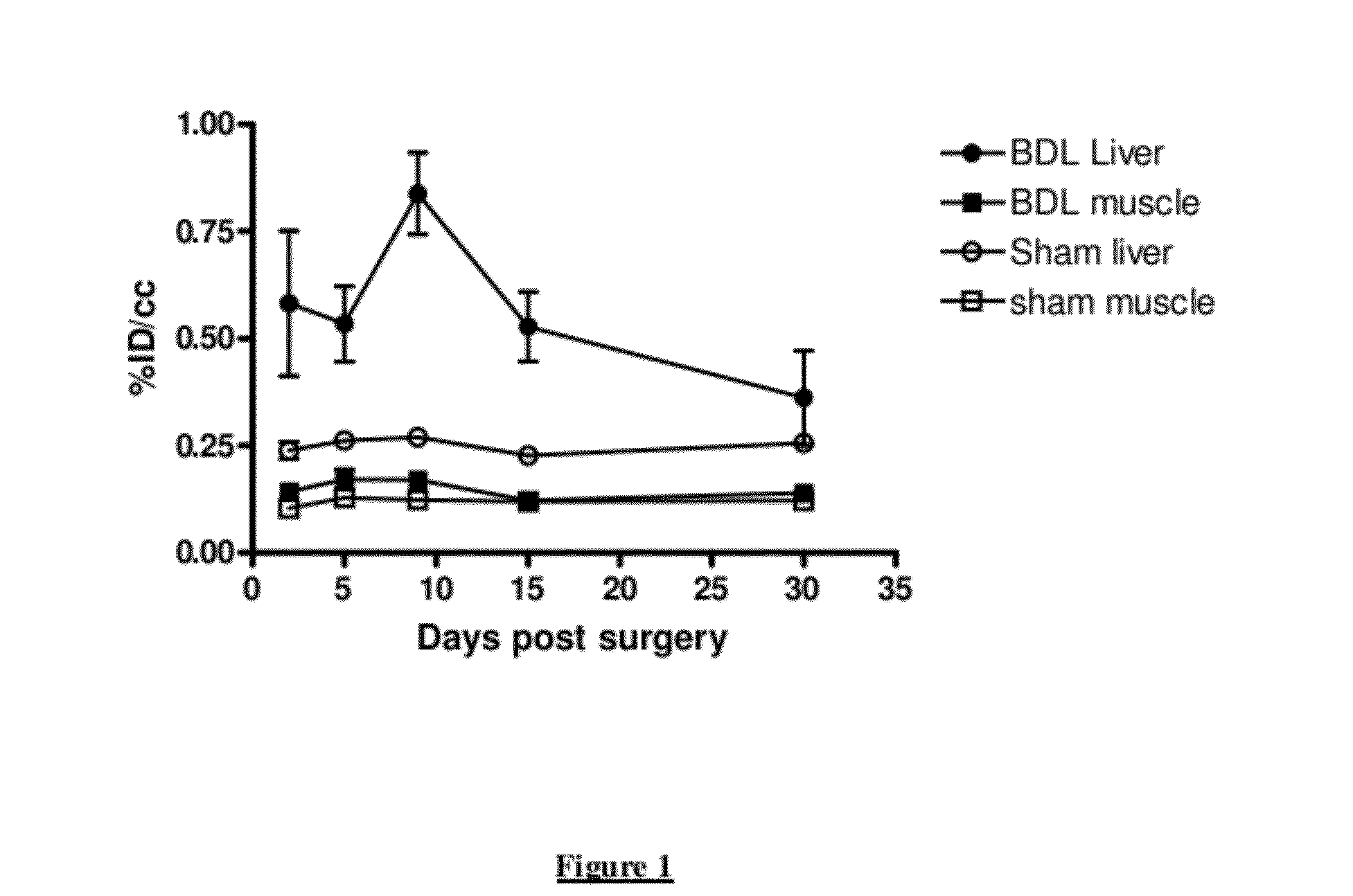
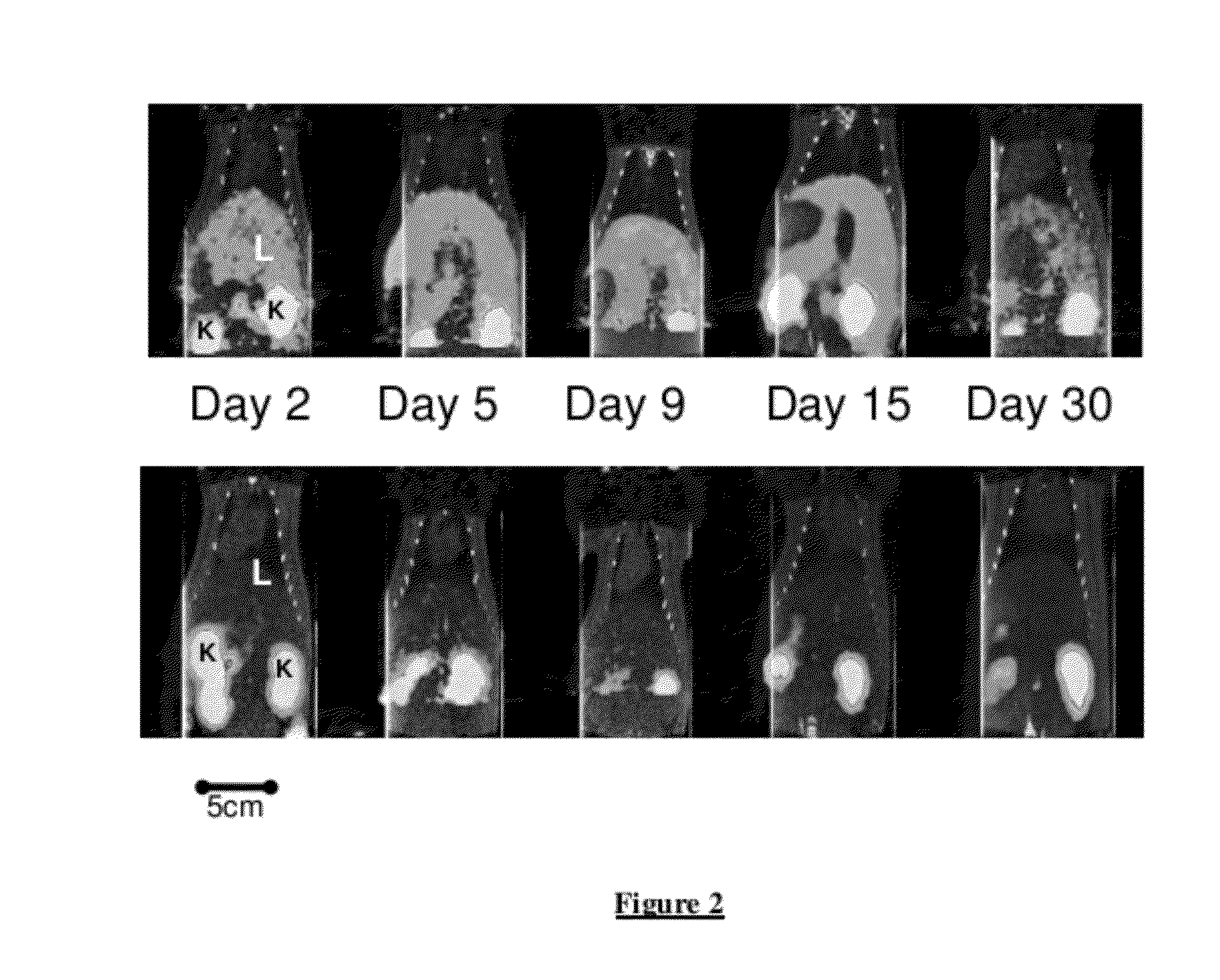
Longitudinal Imaging Studies of PET Tracer 1

[0051]For assessment of PET Tracer 1 in the BDL rat model, static PET images were acquired longitudinally (imaged at 60-90 minutes post-injection) at days 2, 5, 9, 15 and 30 post bile duct ligation surgery or sham surgery. The PET images were co-registered with corresponding CT images.

Prior to the PET image commencing, the histogram and acquisition parameters were inputted into microPET Manager (software controlling data acquisition and processing). The reconstruction parameters were set as follows:[0052]Fourier rebinning algorithm[0053]2D Filter Back Projection with Ramp filter[0054]Image zoom of 2[0055]Scatter correction chosen[0056]Raw image list mode data was saved in Intel / VAX-4-byte float format.

Reconstructed data was saved in .img format (native)

For the image acquisition the parameters were set as follows:[0057]1800 second acquisition (static at 60-90 minutes post-injection)[0058]1 bed position only[0059]Energy windows set at 350-75...


PUM

PropertyMeasurementUnit
energyaaaaaaaaaa
temperatureaaaaaaaaaa
timeaaaaaaaaaa

Abstract

The present invention relates to peptide compounds and their use for in vivo imaging using positron emission tomography (PET). More specifically, the invention relates to the use of such peptide-based compounds in a method for the in vivo imaging of liver fibrosis.

Description

CROSS-REFERENCE TO RELATED APPLICATIONS[0001]This application is a filing under 35 U.S.C. §371 and claims priority to international patent application number PCT / EP2010 / 058135 filed Jun. 10, 2010, published on Dec. 16, 2010 as WO 2010 / 142754, which claims priority to application number 0910013.2 filed in Great Britain on Jun. 10, 2009 and application No. 61 / 185,669 filed in the United States on Jun. 10, 2009.FIELD OF THE INVENTION[0002]The present invention relates to peptide compounds and their use for in vivo imaging using positron emission tomography (PET). More specifically, the invention relates to the use of such peptide-based compounds in a method for the in vivo imaging of liver fibrosis.SUMMARY OF THE INVENTION[0003]The in vivo imaging technique positron emission tomography (PET) provides excellent sensitivity and resolution, so that even relatively small changes in a lesion can be observed over time. A preferred positron-emitting nuclide for use in PET is 18F, which has a ...

Claims


Application Information

Patent Timeline
Patent Type & Authority Applications(United States)
IPC IPC(8): A61K51/00
CPCA61K51/088A61P1/16A61K51/08A61K51/04
Inventor CHETTIBI, SALAHNEWTON, BENSOLBAKKEN, MAGNE
Owner GE HEALTHCARE LTD
Why Eureka
Try Eureka