Single phase power factor correction system and method

Active Publication Date: 2012-05-03
FALLIS DEBORAH LYNN +1
View PDF13 Cites 31 Cited by
  • Summary
  • Abstract
  • Description
  • Claims
  • Application Information

AI Technical Summary

Benefits of technology

[0015]According to yet another aspect of the invention, there is provided a method for reducing load in a controlled manner in an electrical power grid to reduce the likelihood of uncontrolled load shedding in the grid, the grid having an electricity supply, a transmission line connecting said supply to a distribution node, and a number of feeder lines radiating from the distribution node. Each feeder line has a plurality of consumers connected thereto, and each consumer has premises and a single phase electrical panel within the premises. The method comprises the steps of: (i) selecting a set of consumers, the set including a number of cons

Problems solved by technology

Real power measures the ability of an electrical load to perform work in a set time, and is associated with power consumption by a resistive load.
Power distribution networks with a low power factor are undesirable, because they require power lines to carry more current than necessary to provide real power to customers.
The additional current can result in line losses, reduced life span of the equipment and the need to build new power generating facilities.
This can cause power distribution issues.
However, these capacitor banks and other components do not eliminate the majority of the power losses.
Many of these components and capacitors are also large, difficult to install, suffer from transient breakdown, require extra infrastructure, and need expensive on-going maintenance.
However, a static capacitor bank has no control capabilities, and a capacitance constantly on-line can be detrimental to the distributing system, by causing higher line current at periods of low usage by the consumers.
In addition, severe adverse conditions can arise in tran

Method used


Image

  • Single phase power factor correction system and method
  • Single phase power factor correction system and method
  • Single phase power factor correction system and method

Examples


Embodiment Construction

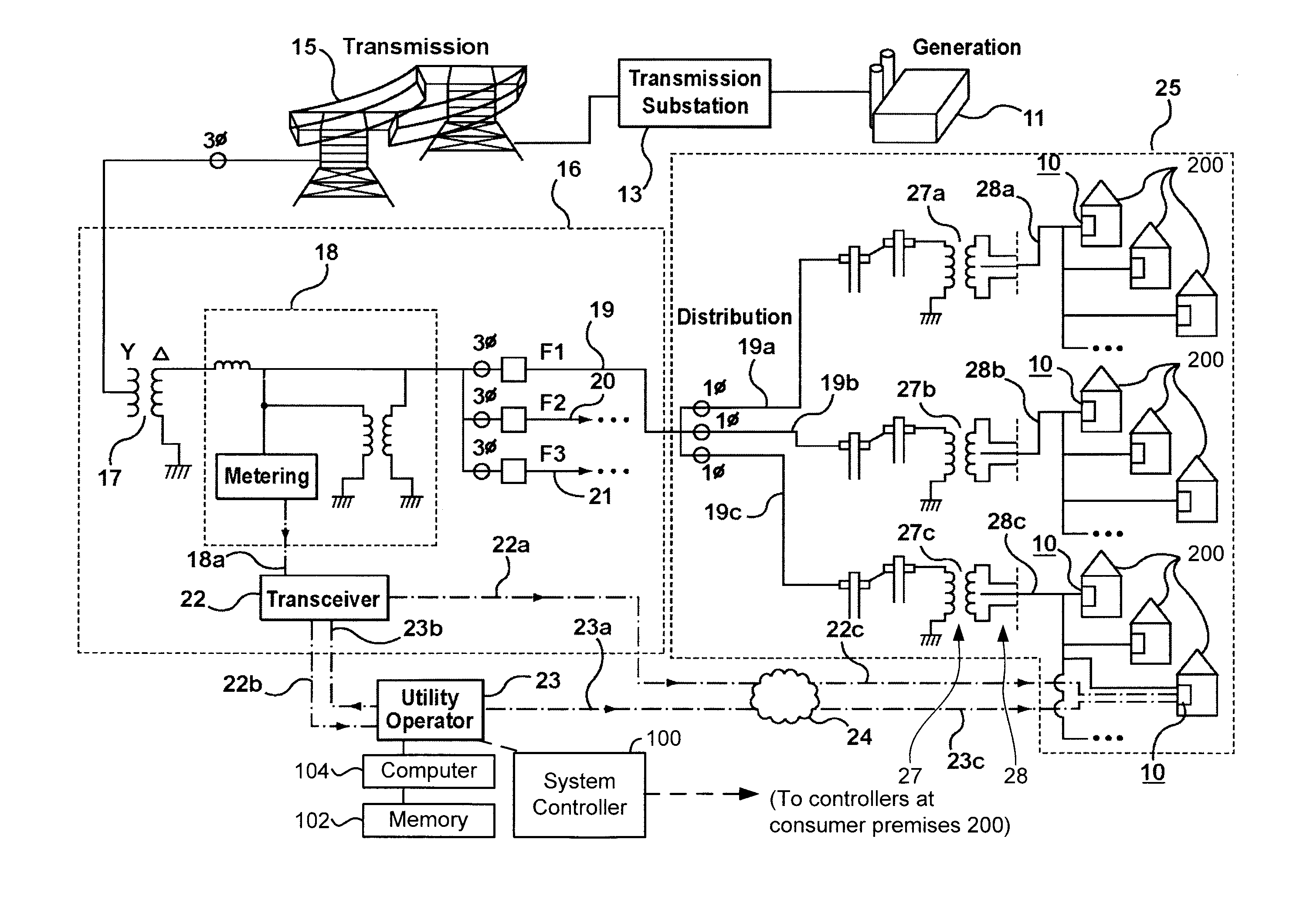
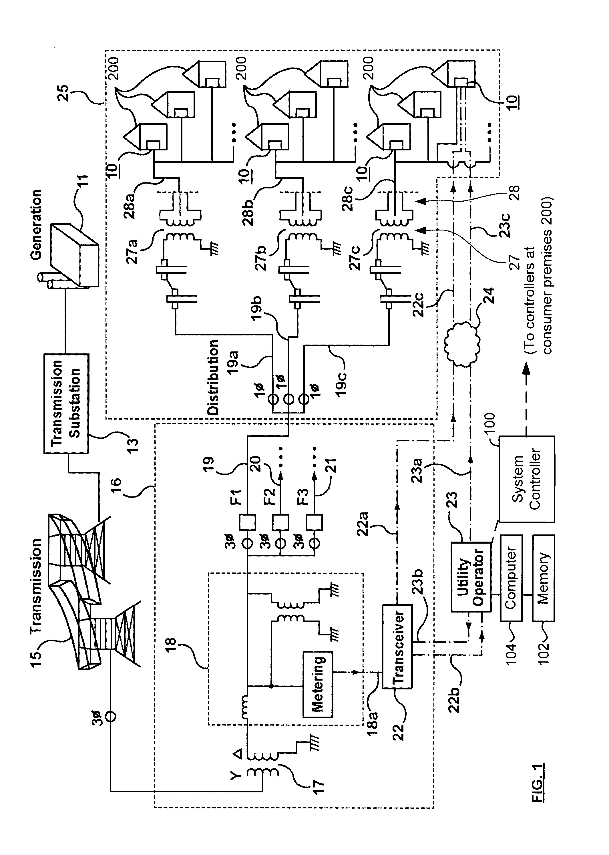
[0021]Referring now to FIG. 1, a plurality of single phase grid correction systems 10 made in accordance with an embodiment of the present invention are shown incorporated into an exemplary electrical power network that provides electrical power to consumers 200 having a single phase electrical panel. The power network includes electric power generators 11, such as hydro-electric, coal or nuclear power plants. (The power network can also include connections to another power network in an adjacent area, and from which power is being purchased on an emergency, or temporary basis, or on a permanent basis.) The generated electrical power is fed to transmission substations 13 comprising transformers, relays and circuit breakers to convert the power to higher voltages for transmission. This is important because higher voltages result in less power loss according to Joule's law. Electrical power is then transmitted at high voltage in three-phase alternating current form, across the transmi...


PUM


Abstract

A single phase grid correction system for correcting the power factor of an electrical power grid. The grid has a generator, transmission lines connecting the generator to distribution nodes, feeder lines radiating from each node, and groups of consumers connected to each feeder line. A capacitor bank is located at a number of consumer's premises, indoors, either beside or forming part of the consumer's normal single phase electric panel. A set of remotely controlled switches at the consumer's premises permits the capacitor banks to be switched in and out of grid connection and also allows non-essential high energy consuming loads, not necessarily inductive, to be switched on and off the grid. The grid correction systemic are widely distributed at consumer's premises throughout the grid. By remotely controlling the switches, the utility operator can switch capacitor banks at selected consumer premises in or out of the grid to provide or remove reactive power as needed, and can also selectively remove load from the grid to reduce the likelihood of sudden uncontrollable load shedding.

Description

FIELD[0001]The present invention relates to apparatus and a method for enhancing the efficiency of power systems. In particular, it relates to apparatus and a method for reducing transmission losses in electrical power transmission and distribution systems, and for reducing electrical power demand during peak times and assisting in electrical power transactions.BACKGROUND[0002]The power factor is the ratio of real power to apparent power in a transmission and distribution system. It is used by the power industry to gauge the efficiency of a power distribution system. Real power measures the ability of an electrical load to perform work in a set time, and is associated with power consumption by a resistive load. Reactive power is associated with power generated by the impedance of a reactive load, which can be inductive or capacitive. The apparent power is the sum of the real power and the reactive power and may be equal to or greater than the real power depending on the parasitic re...

Claims


Application Information

Patent Timeline
IPC IPC(8): H02J3/00
CPCH02J13/0075Y02E40/74Y04S10/22Y10T307/406Y02E60/7853H02J3/1828Y02E40/30Y04S40/126H02J13/00024H02J13/00034Y02E40/70Y02E60/00
Inventor FALLIS, DEBORAH LYNNBEUTHLING, MISCHA WARREN
Owner FALLIS DEBORAH LYNN
Why Eureka
Try Eureka