Double-walled carbon nanotubes and methods for production and application

a carbon nanotube and double-walled technology, applied in the manufacture of electrode systems, fullerenes, electric discharge tubes/lamps, etc., can solve the problems of large number of layers, difficult control of the number of layers, and the electronic properties and applications of nanotubes are not less attractiv

Inactive Publication Date: 2012-05-03
ATS MER LLC
View PDF1 Cites 31 Cited by
  • Summary
  • Abstract
  • Description
  • Claims
  • Application Information

AI Technical Summary

Benefits of technology

[0015]It is a primary object of the present invention to provide a new material comprising a carbon nanotubule having two nearly cylindrical graphene layers.
[0016]It is an object of the present invention to provide novel methods for making macroscopic quantities of controlled number of layers nanotubes.
[0017]It is another object of the present invention to provide novel methods for making in particular substantially pure double walled nanotubes.
[0018]It is still further object of the present invention to provide novel methods for making in particular substantially pure double walled nanotubes.
[0019]It is yet a further object of the present invention to provide novel electron emitting carbon structures embodying such double walled nanotubes, which are suitable for making cold cathodes for field emission displays and vacuum microelectronic devices, it is a further object of the present invention to provide novel solid field emission cathode structures embodying such electron emitting carbon structures.
[0020]It is more specific object of the present invention to provide a novel light emitting CRT embodying carbon double walled nanotube material the electron emitting structures of the cathode.

Problems solved by technology

Indeed these are materials of such widespread interest that the application development has out-paced its mass availability.
However, the numbers of layers are very difficult to control.
The electronic properties and applications of nanotubes are not less attractive.
The MWNTs are very robust in low vacuum and thus meet this requirement, while SWNTs fail to perform the same perfectly, because of lower robustness to degradation at high currents.
No other means for their identification or property studies was ever employed, as DWNTs have not been available as a matter substance, even in microgram scale, nor could any their amount be separated from the mixture of said carbon products for positive identification.

Method used


Image

  • Double-walled carbon nanotubes and methods for production and application
  • Double-walled carbon nanotubes and methods for production and application
  • Double-walled carbon nanotubes and methods for production and application

Examples


example 1

[0084]This example presents optimized conditions for high yield of DWNTs.

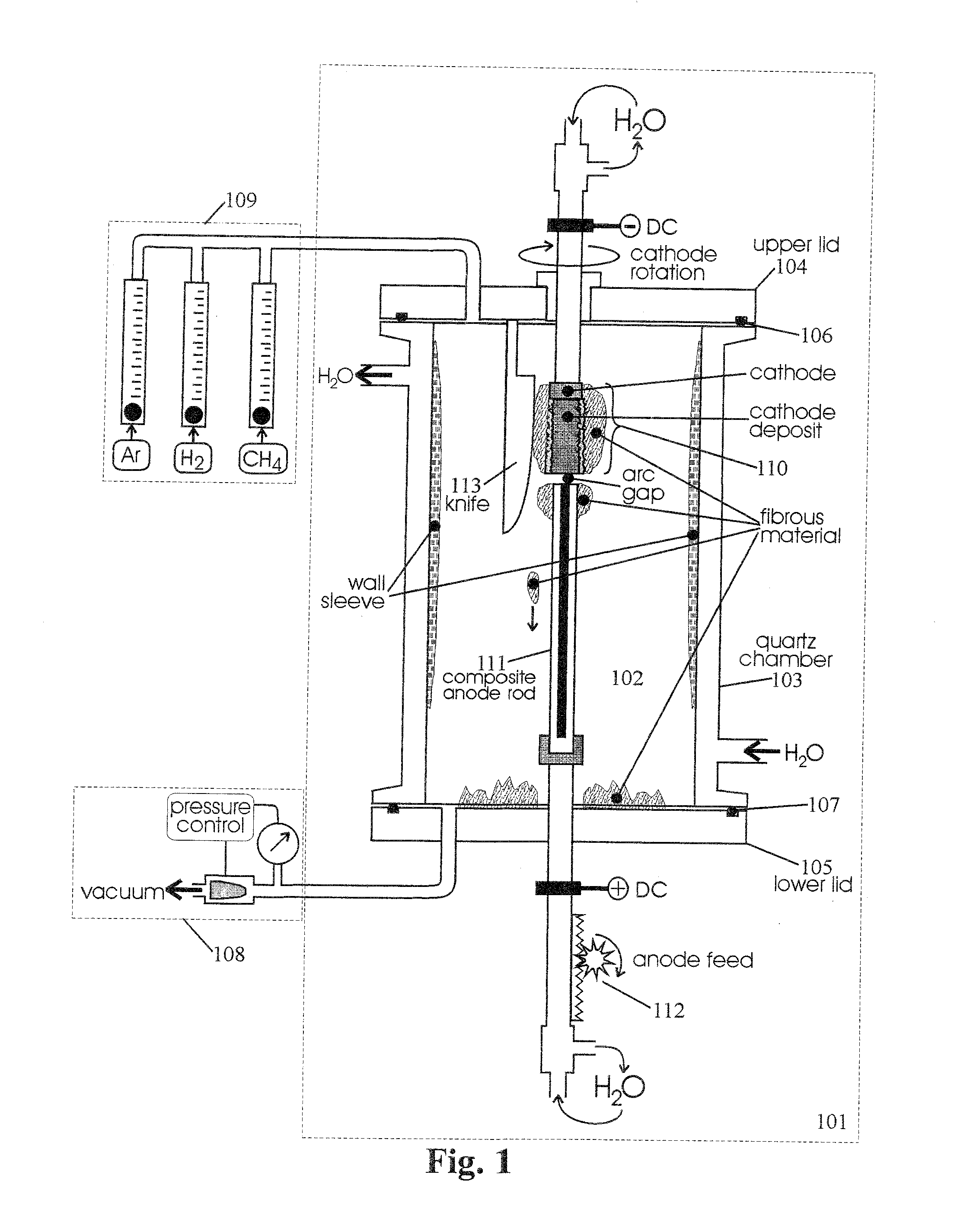
[0085]Preparation of the catalyst. The mixture of fine metal powders of iron (81.0 g, 2-5 μm particle size), cobalt (41.3 g, 2-5 μm), nickel (152.6 g, 2-5 μm) and elementary sulfur (24.1 g) is heated to 750° C. at a rate 30° C. / min and maintained at this temperature for 30 min in the flow of H2 (20 sccm) and He (30 sccm) at atmospheric pressure in a quartz tube 80 mm in diameter, then cooled down to room temperature. The resultant strong crisp lump of greenish-brown color is ground in a ball mill to a powder with particle size ca. 1-2 μm. This powder is mixed with 75.0 g of fine graphite powder (SUPERIOR GRAPHITE, BG-34).

[0086]Preparation of consumable anode. A graphite rod 210 mm long, 7.93 mm in diameter and of 1.78 g / cm3 density is drilled to 200 mm depth along the axis with a drill 3.18 mm in diameter, and the resultant hole is densely packed with 5.5 g of the catalyst prepared as described above. The calcu...

example 2

[0094]This example demonstrates the negative effect of deviation from he optimal value of the total pressure on the yield and quality of DWNTs.

[0095]The catalyst and experimental conditions are the same as in EXAMPLE 1, except that total gas pressure in the chamber was maintained equal to 700 Torr during the process.

[0096]As a result, the yield of fibrous material has dropped down to 0.18 g (ca. 1.0% of consumed anode). These fibers are weak and easily disintegrate into a powder by crinkling in fingers. The content of DWNTs and SWNTs in the fibrous material is about 5%, the rest is mainly amorphous carbon and metal nanoparticles. The ration DWNTs / SWNTs in the fibrous material is about 1. The wall sleeve is very loose and powdery. It contains about 1% of carbon nanotubes, DWNTs and SWNTs.

example 3

[0097]This example demonstrates the negative effect of deviation from the optimal value of electric current on the yield and selectivity of DWNT production.

[0098]Conditions are the same as in EXAMPLE 1, except that electric current value was maintained equal to 75 A.

[0099]As a result, the yield of fibrous material is 0.65 g (ca. 3.5% of consumed anode). The total yield of DWNTs and SWNTs in the fibrous material is about 60%, the rest is amorphous carbon and metal nanoparticles (FIG. 6). The amount of DWNTs and SWNTs is about equal in the sample of the fibrous material. The same is observed in the wall sleeve material, the ration DWNTs / SWNTs is about 1.


PUM

PropertyMeasurementUnit
pressureaaaaaaaaaa
inner diameteraaaaaaaaaa

Abstract

The present invention relates to fullerene carbon nanotubes having a cylindrical wall comprising a double layer of carbon atoms and methods for the production and application of these double-wall carbon nanotubes; and, more particularly, to nanotubes with controlled number of carbon layers and methods for the production of macroscopic amounts of these nanotubes and there application as cathode materials in the cold field electron emission devices, notable such devices comprising light emitting CRT's.

Description

[0001]The present invention relates to fullerene carbon nanotubes having a cylindrical wall comprising a double layer of carbon atoms and methods for the production and application of these double-wall carbon nanotubes; and, more particularly, to nanotubes with controlled number of carbon layers and methods for the production of macroscopic amounts of these nanotubes and to novel cold field electron emission devices embodying such nanotubes.BACKGROUND OF THE INVENTION[0002]Because of their unique mechanical and electric properties, the recently discovered fullerene nanotubes, both Single-Walled Nanotubes (SWNTs) and Multi-Walled Nanotubes (MWNTs) have been investigated for many applications. Indeed these are materials of such widespread interest that the application development has out-paced its mass availability. The most added-value applications that are being developed using nanotubes include Field Emission Devices, Memory devices (high-density memory arrays, memory logic switchi...

Claims


Application Information

Patent Timeline
Patent Type & Authority Applications(United States)
IPC IPC(8): D01F9/12B82B1/00B82B3/00C01B31/02D01F9/127H01J9/02
CPCB82Y10/00B82Y30/00B82Y40/00C01B2202/04D01F9/127H01J9/025H01J2201/30469Y10T428/292C01B32/152C01B32/162B82B3/00C01B32/05H01J1/30
Inventor MORAVSKY, ALEXANDER P.LOUTFY, RAOUF O.
Owner ATS MER LLC
Why Eureka
Try Eureka