Method and Apparatus for Providing a Machine Barrel with a Heater

a technology of heater and machine barrel, which is applied in the field of equipment for providing a machine barrel with a heater, to achieve the effect of improving the thermal contact of the wir

Inactive Publication Date: 2012-05-10
AMERICAN ROLLER
View PDF2 Cites 5 Cited by
  • Summary
  • Abstract
  • Description
  • Claims
  • Application Information

AI Technical Summary

Benefits of technology

[0027]The invention provides a barrel adapted for use in a machine, the barrel having a heater for energization to heat a material within the machine, the barrel further comprising an inner layer of insulating ceramic disposed over and around the barrel along its length to form an insulated barrel; a wire layer including a plurality of heating coils of alloy resistance wire wound around the insulated barrel under ...

Problems solved by technology

Because the contact of the heater to the barrel surface is imperfect, basically only a few line contacts, the heat transfer from the band heater is relatively inefficient causing temperature excursions inside the band heater.
The parts of the heater not in actual contact with the barrel can overheat and burn out under high thermal loads.
For processes that do not require cooling, insulation cannot normally be used over a band heater, because it promotes overheating in low heat transfer areas of the heater.
The cost of the band heater is based on watt density, operating temperature, and barrel size.
Some of the larger units can be quite expensive.
The poor thermal contact of the band heater to the barrel also affects the cooling rate.
The thermal contact of the aluminum shells to the extruder barrel is composed of a series on line contacts and is therefore not as efficient as desired for heating or cooling.
The aluminum shells also have considerable thermal mass when attempting to heat or cool a barrel section.
They are also quite expensive although durable.
It is efficient, produces much more uniform temperatures than band heaters, but is quite expensive.
It is currently only used in applications that do not require cooling, since a cost effective way to cool an induction heated zone has not been devised.
The existing heater technologies for extruder barrels that are either bolted, banded, or clamped to the outside surface of the extruder barrel may have these limitations:1) Limited heater to barrel contact and therefore limited heat transfer rates, heating or cooling;2) Significant non-uniformity in temperature at the in...

Method used


Image

  • Method and Apparatus for Providing a Machine Barrel with a Heater
  • Method and Apparatus for Providing a Machine Barrel with a Heater
  • Method and Apparatus for Providing a Machine Barrel with a Heater

Examples


first embodiment

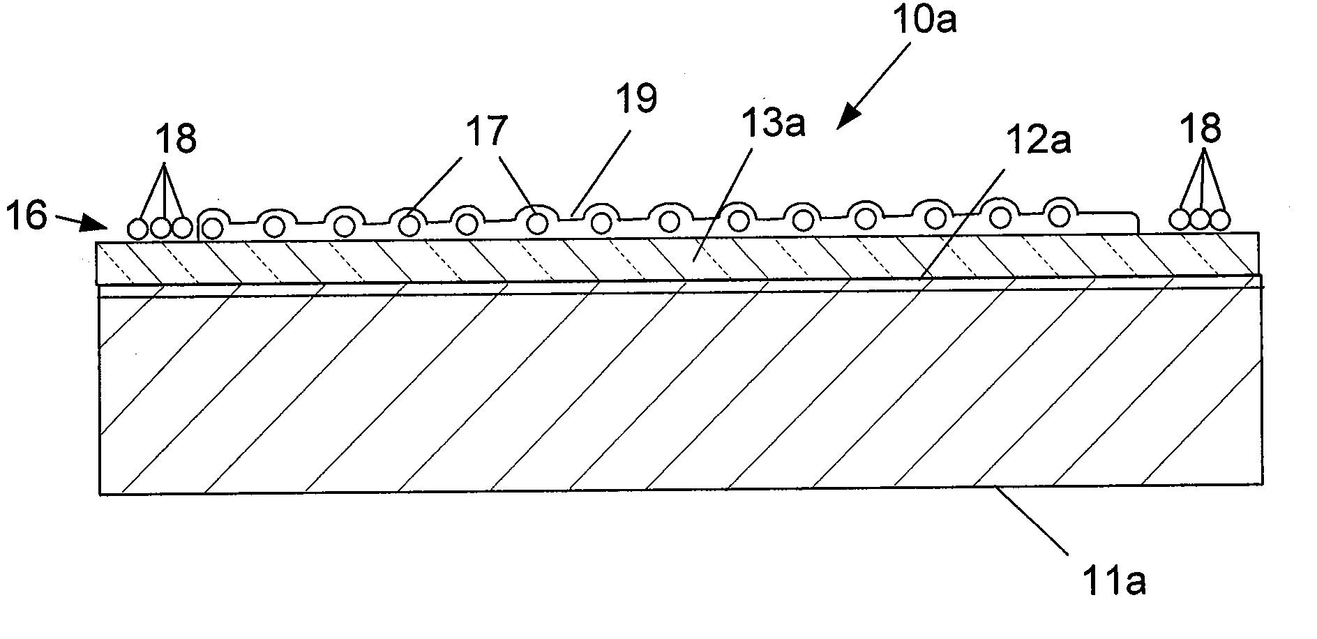
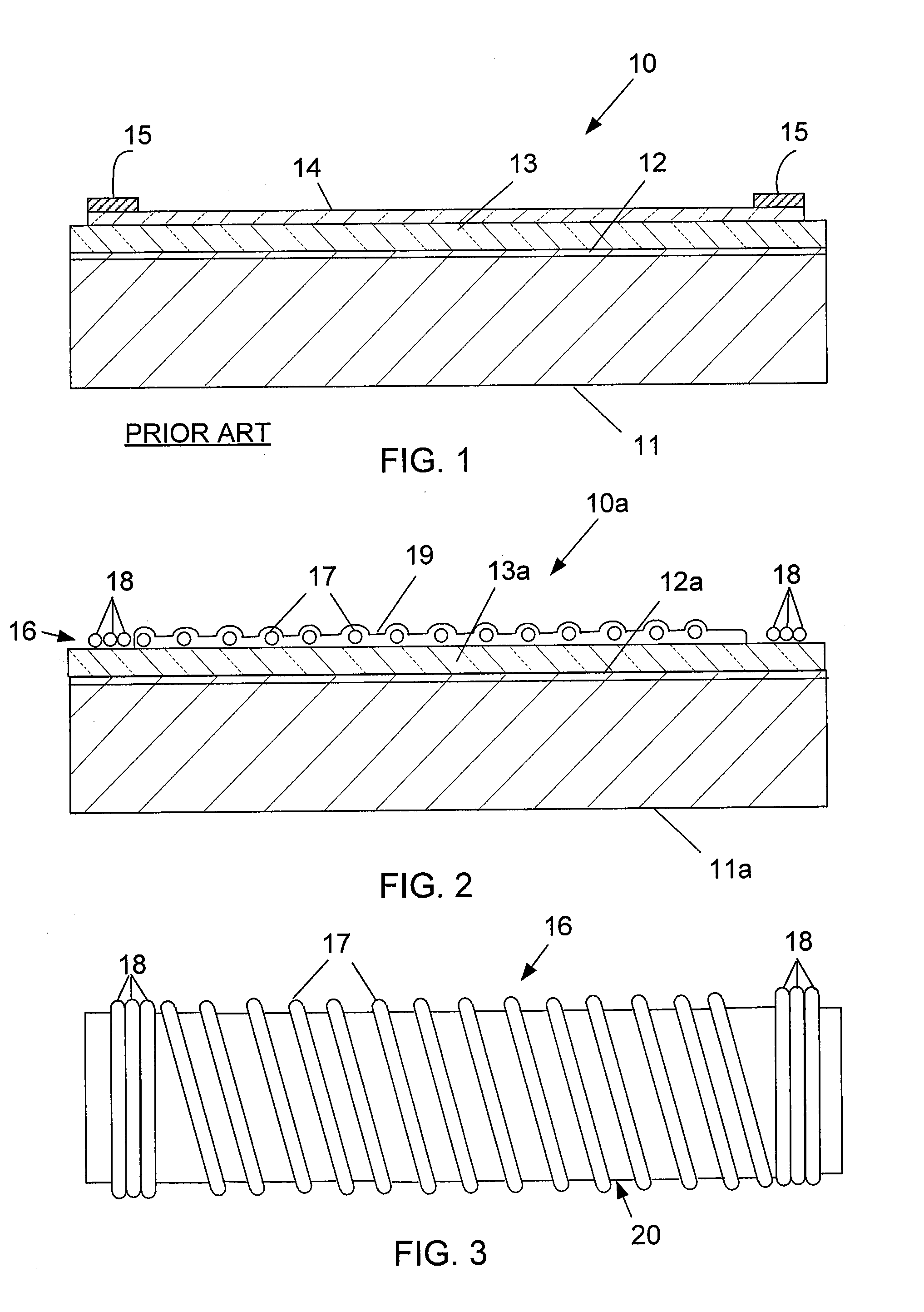
[0036]As seen in FIG. 1, in a barrel heater 10, an extruder barrel 11 of mild steel, to which the heater sections will be applied, is first grit blasted to a 250 microinch Ra finish or higher. Extruders are used to process many kinds of materials, but the primary uses are for forming and shaping thermoplastic polymers (plastics) and elastomeric polymers (rubber compounds). Material to be extruded is initially deposited in a solid form into a feedbox. The material exits the extruder as a hot, uniform viscosity, semi-molten solid by being pushed under high pressure (extruded) through a die. The die gives the extruded material (extrudate) its cross sectional shape. Next, in forming the barrel, a thin layer of a metal bonding alloy 12 is plasma or thermal sprayed over the entire barrel (covering all heated zones) such as Sulzer Metco 450 or 480 nickel aluminide bond coat in a thickness of 3-5 mils. Areas of the barrel may need to be masked to prevent adhesion of the bonding alloy such a...

second embodiment

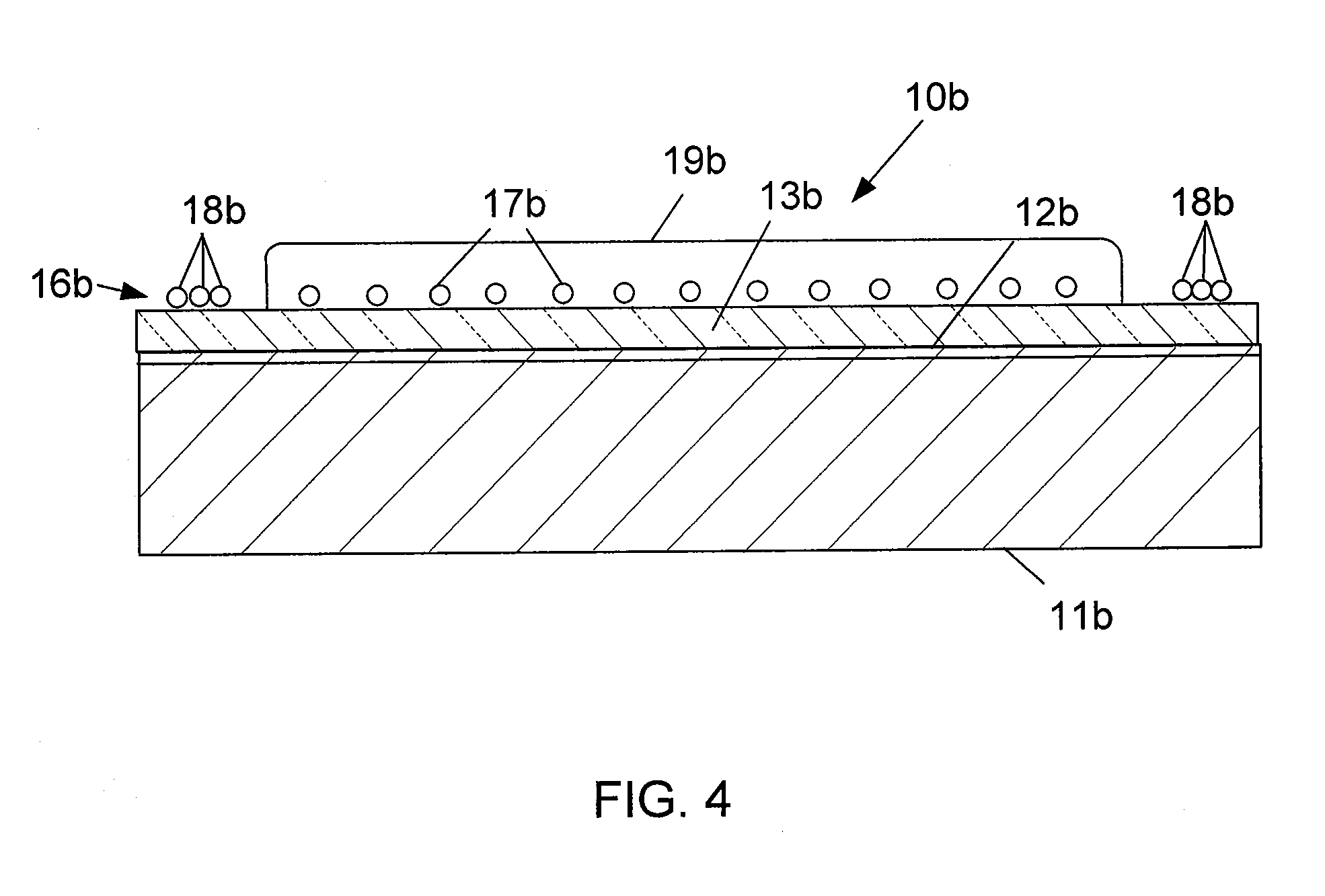
[0044]FIG. 4 illustrates the invention in which the top ceramic layer 19b has been expanded to be a relatively thick layer which is ground (although it does not have to be ground to be functional) to provide a smooth surface and a uniform thickness using a diamond-coated or other suitable grinding wheel. The thickness of the layer 19b above the tops of the wires 17b is about the same thickness as the wires 17b after the layer has been ground to provide a smooth surface. Layers 13b, 16b, and 19b above the wires 17b, could all be 20-25 mils thick each, for example. The thick top ceramic layer 19b improves heat transfer from the wires 17b into the barrel 11b, makes a more durable composite layer which will withstand abuse and impacts, provides electrical insulation over the current-carrying heater wires 17b, and provides a smooth surface on which to apply a conventional band heater in the event that the ceramic-wire heater fails or is damaged in some way. The extruder barrel 11b is aga...


PUM

PropertyMeasurementUnit
Lengthaaaaaaaaaa
Thicknessaaaaaaaaaa
Lengthaaaaaaaaaa

Abstract

A barrel (11a, 11b) adapted for use in a plastics machine, has an inner layer of insulating ceramic (13a, 13b) disposed over and around the barrel along its length to form an insulated barrel, a wire layer (16, 16b) including a plurality of heating coils (17, 17b) of alloy resistance wire wound around the insulated barrel under tension in a spiral fashion, the wire layer also providing additional termination coils (18, 18b) near opposite ends of the barrel for making electrical contact with a source of electrical power to heat the barrel, and a top layer (19, 19b) of an electrically insulating ceramic disposed over the heating coils A method of making a barrel with a heater, comprises spraying a layer (12, 12b) of a metal bonding alloy over a portion of the barrel to be heated.

Description


Claims


Application Information

Patent Timeline
IPC IPC(8): F27D11/02H05B1/00B23P19/04
CPCB29C47/0016B29C47/66Y10T29/49002H05B3/46B29C47/82B29C48/875B29C48/83B29C48/06B29C48/68
Inventor HYLLBERG, BRUCE E.
Owner AMERICAN ROLLER
Why Eureka
Try Eureka