
Vacuum flourescent display apparatus

Inactive Publication Date: 2012-05-10
NORITAKE ITRON CORP +1
View PDF7 Cites 0 Cited by
  • Summary
  • Abstract
  • Description
  • Claims
  • Application Information

AI Technical Summary

Benefits of technology

[0013]An object of the present invention is to improve the lifespan characteristics of the phosphor, and in particular, to enhance the lifespan characteristics when a red phosphor that does not contain Cd is driven in a voltage range of 30V or above. As a result, the lifespan characteristics of a vacuum fluorescent display apparatus made using the phosphor are enhanced.
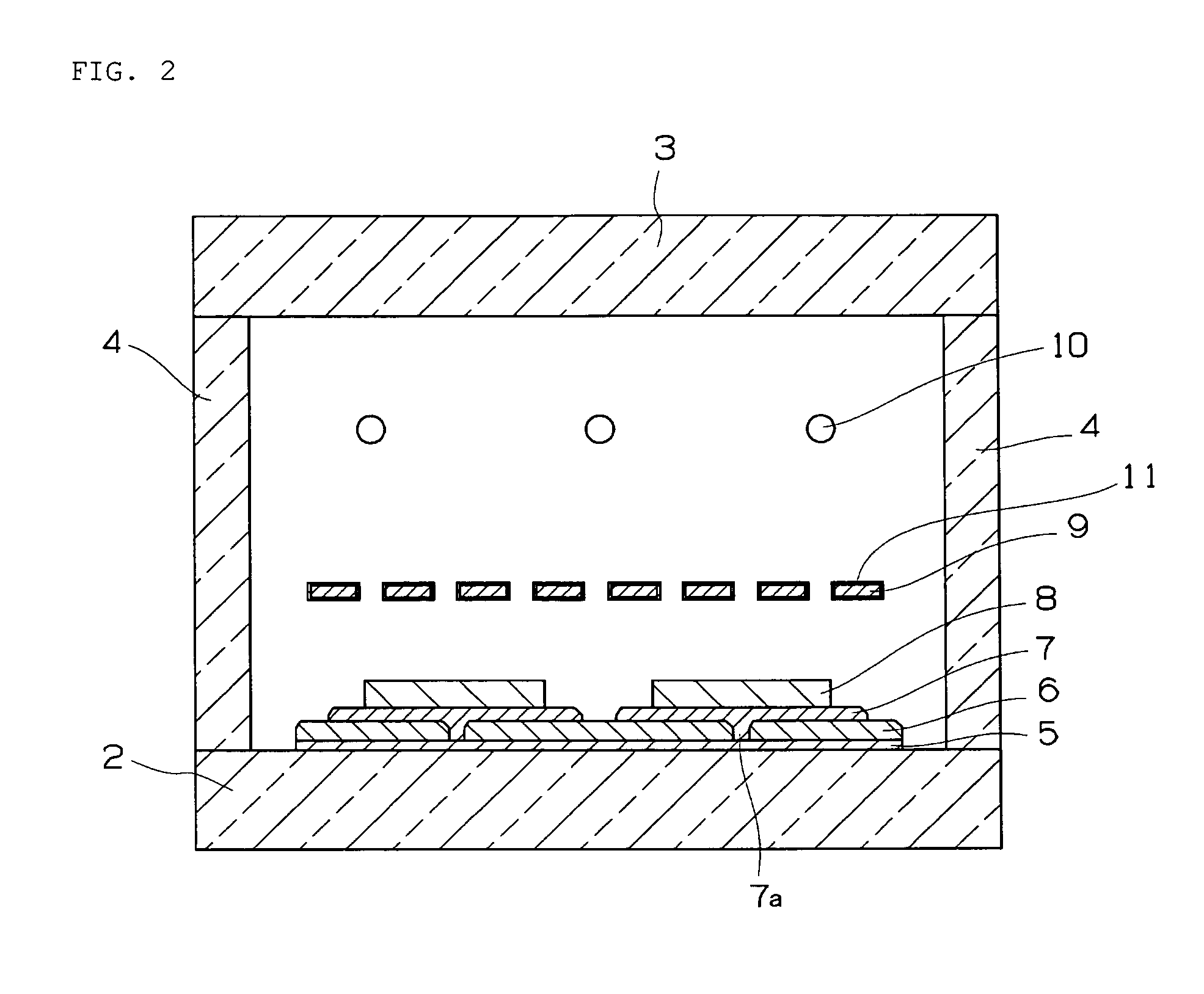
[0021]Barium, which adversely affects the phosphor, is thereby trapped by the structural body. As a result, degradation of the phosphor is inhibited and the lifespan characteristics are improved. In particular, lifespan characteristics of a red phosphor at a voltage of 30V or above are significantly improved.
[0022]Also, according to the methods, described in (2) and (3) above, for improving the lifespan characteristics of an oxide-based red phosphor, a getter material is installed in a vacuum container in order to enhance the level of vacuum in the vacuum container. Therefore, according to this method, the getter material must be subjected to a separate activation treatment. In contrast, according to the present invention, the surface of the electrically conductive or semi-conductive metal oxide is bombarded with electron beams. Therefore, lifespan characteristics of the phosphor can be enhanced without performing a separate activation treatment.

Problems solved by technology

Therefore, a decrease in display quality due to degradation of a red phosphor occurs not only in instances in which only red phosphor is used, but also in instances in which a red phosphor is combined with a phosphor corresponding to another color and a mixture of colors is used.
Accordingly, there is a significant decrease in the lifespan of a vacuum fluorescent display apparatus in which a red phosphor of such description are used.
However, the lifespan of a vacuum fluorescent display apparatus made using an oxide-type red phosphor treated as described above remained extremely low compared to that of ZnCdS-based phosphors.
However, increasing the amount of protecting film adhered onto the surface of an oxide-based red phosphor results in a decrease in brightness.
As a result, the lifespan of the vacuum fluorescent display apparatus cannot be enhanced.

Method used


Image

  • Vacuum flourescent display apparatus
  • Vacuum flourescent display apparatus
  • Vacuum flourescent display apparatus

Examples


example 1

[0080]A description will be given for an example in which an oxide that readily forms a compound with barium is provided on a surface of a mesh-shaped grid electrode (hereafter referred to as a “mesh”).

[0081]Using an organic metal compound made from titanium (Fuji Kagaku Corporation; Hautform RD-Ti), a solution that has been diluted with ethanol so that the titanium oxide concentration is equal to 2 weight percent is prepared in a beaker or a similar glass container. Other than ethanol, the solution can also be diluted with isopropyl alcohol, terpineol, or another organic solvent.

[0082]A mesh, made from alloy 426, to be used for the grid electrode is immersed in the prepared solution. The immersed mesh is extracted, and excess solution remaining on the surface is blown off using a blower so that the mesh is coated by the solution in a uniform manner. The mesh is then dried, thereby causing an organic metal compound made from titanium to adhere to the mesh.

[0083]The mesh, having the ...

examples 2 through 5

[0088]A vacuum fluorescent display apparatus is produced using the same method as that used in the example 1, except that the following organic metal compounds are used on the mesh surface, and subjected to the same evaluation as that for the example 1. The results are shown in Table 1.

[0089]Example 2: An organic metal compound made from zinc (Fuji Kagaku Corporation; Hautform RD-Zn)

[0090]Example 3: An organic metal compound made from tungsten (Fuji Kagaku Corporation; Hautform RD-W)

[0091]Example 4: An organic metal compound made from tin (Fuji Kagaku Corporation; Hautform RD-Sn)

[0092]Example 5: An organic metal compound made from molybdenum (Fuji Kagaku Corporation; Hautform RD-Mo)

example 6

[0102]A vacuum fluorescent display apparatus is produced using the same method as that used in the example 1, except that an oxide made from titanium is formed by sputtering on the grid. The same evaluation as that for the example 1 is performed.

[0103]Sputtering is performed by high-frequency sputtering using a titanium oxide target (Furuuchi Chemical Corp.). Sputtering is performed by draining the chamber of air, then introducing Ar gas and applying an RF power (with a frequency of 13.56 MHz) at 150 W.

[0104]As a result of performing the same evaluation as that for the example 1, it was found that adheringly forming titanium oxide by sputtering results in an effect similar to the example 1 in which titanium oxide is adheringly formed by dipping.


PUM


Abstract

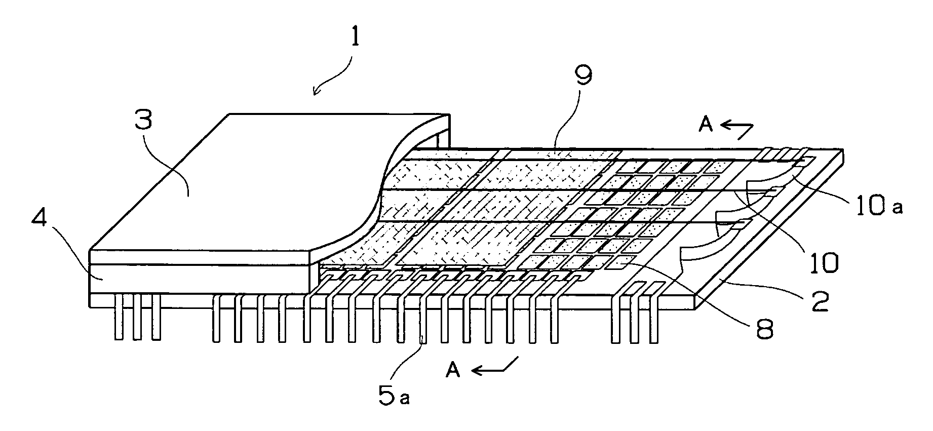
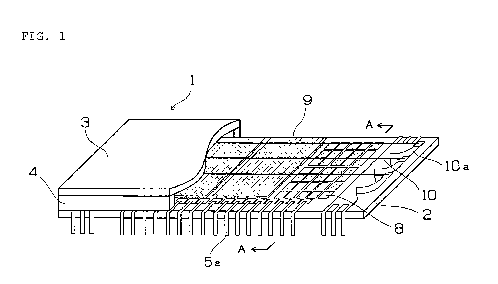
To provide a vacuum fluorescent display apparatus that can be expected to enhance lifespan characteristics of a red phosphor that does not contain Cd when driven in a voltage range of 30V or above.A vacuum fluorescent display apparatus comprising a filament cathode (10) and an anode (7); the filament cathode being arranged in a vacuum container, and used for releasing low-energy electrons; the anode having a phosphor (8) adhering thereto, and being struck by the low-energy electrons and thereby caused to emit light; wherein a structural body (9) is provided to a region in which the low-energy electrons released by the cathode can be controlled; the structural body having an electrically conductive or semi-conductive metal oxide formed at a portion that is bombarded by low-energy electrons.

Description

BACKGROUND OF THE INVENTION[0001]1. Field of the Invention[0002]The present invention relates to a vacuum fluorescent display apparatus, comprising a phosphor for a low-energy electron beam as a light source.[0003]2. Description of the Related Art[0004]Phosphors that are excited by low-energy electron beams and that are used in vacuum fluorescent display apparatuses include phosphors in which an oxygen atom is included in the chemical formula of the parent material. Examples of phosphors of such description include ZnO, Ca(1-x)SrxTiO3:Pr,M (where 0≦x≦1 and M is at least one type of metal selected from Al, Ga, In, Mg, Zn, Li, Na, and K), or Ln2O2S:Re (where Ln is at least one type of metal selected from La, Gd, Y, and Lu; and Re is Eu, Tb, or Sm). Phosphors of such description are prone to degradation in brightness caused by barium generated by evaporation from a filament cathode.[0005]In particular, oxide-based red phosphors that do not contain Cd suffer from significant degradation...

Claims


Application Information

Patent Timeline
IPC IPC(8): H01J63/04
CPCH01J31/15H01J2329/20C09K11/7789C09K11/7703H01J2329/943
Inventor KATO, KOJI
Owner NORITAKE ITRON CORP
Learn More