Systems and methods for thermal management of electronic components

a technology of electronic components and thermal management, applied in the direction of insulated conductors, cables, lighting and heating apparatus, etc., can solve the problems of insufficient heat transfer efficiency, inability to achieve the effect of facilitating thermal energy transfer, and reducing the number of contact points of the interface, so as to facilitate the transfer of thermal energy, facilitate the dissipation of heat, and enhance the effect of heat dissipation

Inactive Publication Date: 2012-05-17
NANCOMP TECHNOLOGIES INC
View PDF14 Cites 25 Cited by
  • Summary
  • Abstract
  • Description
  • Claims
  • Application Information

AI Technical Summary

Benefits of technology

[0013]In some embodiments, the device further comprises an adhesive to maintain the electrically conductive member on the thermally conductive member. In some embodiments, the device further comprises fins to help facilitate the transfer of thermal energy away from the heat source.
[0014]The present invention, in one aspect, is directed to a method of dissipating heat from a heat source, such as a conductor. In some embodiments, a thermally conductive layer may be situated against a heat source, to dissipate heat while an electrically conductive layer may be positioned about the thermally conductive layer. A pattern may be imparted to the electrically conductive layer to enhance dissipation of heat away from the heat source.

Problems solved by technology

However, the use of flat plates at the interface to facilitate the heat transfer from the integrated circuit to the heat sink has proved not to be optimal.
As a result, the heat that flows out of the hot integrated circuit can only pass through these few contact spots.
In particular, since they operate at low loads and have a very low resistance, fibers structures can dissipate relatively much more heat than a smooth surface.

Method used


Image

  • Systems and methods for thermal management of electronic components
  • Systems and methods for thermal management of electronic components
  • Systems and methods for thermal management of electronic components

Examples


example 1

[0056]FIG. 5 shows a graph comparing the frequency and resistivity of carbon nanotube wires with the frequency and resistivity of Aluminum and Copper wires. Specifically, this experiment was conducted using a 6-ply non-insulated carbon nanotube wire and 35 AWG gauge Aluminum and Copper wires at 20° C. and 100° C. The electrical measurements performed were conducted with less than about 1 Watt.

[0057]As shown in FIG. 5, bulk materials composed of carbon nanotubes exhibit improvements in conductivity at higher frequencies. For example, at about 1.E+05 Hz, bulk materials composed of carbon nanotubes exhibit a drop in resistivity from about 1.E-04 Ω-cm to about 1.E-05 Ω-cm. In some cases, carbon nanotube wires may be doped for better electrical behavior.

example 2

[0058]An experimental setup for testing the temperature versus power of the thermal management devices included using two sets of carbon nanotube wires. The first set included two six-inch samples of non-insulated large diameter carbon nanotube wires. The diameters of the carbon nanotube wires includes plies of 25 (˜29 AWG), 50 (˜26 AWG), 100 (˜23 AWG), and 150 (˜21 AWG). These carbon nanotube wires were formed and plated with nickel followed by copper on both ends. The second set included the same diameter carbon nanotube wires that were insulated with a zero inner diameter shrink tubing rated to 300° C. Each set was hung in air, and a DC power supply was used to run current through and a voltage across the sample. The Power applied ranged from about 0 Watts to about 10 Watts. The power supply was set to be current limiting and readings were taken every half volt once the temperature stabilized. The temperature measured ranged from about 0° C. to about 200° C. The temperature was m...

example 3

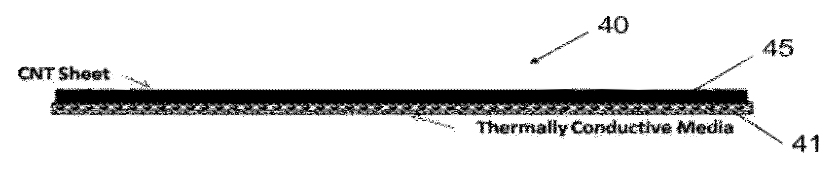
[0060]An experimental setup for testing the temperature versus power of the thermal management devices included using a sheet of carbon nanotube electrical conductor (i.e., electrically conductive member) and laminating with a thin layer of a high thermally conductive graphite (i.e., thermally conductive member). The resulting laminated structure was then rolled tightly to form a cylinder approximately six inches long. The sample was hung in air, and a DC power supply was used to run a current through and a voltage across the sample. The Power applied ranged from about 0 Watts to about 10 Watts. The power supply was set to be current limiting and readings were taken every half volt once the temperature stabilized. The temperature measured ranged from about 0° C. to about 200° C. The temperature was measured with Wahl Heat Spy HSI3000 Thermal Imager. The response is shown in FIG. 7 and is compared to the pure carbon nanotube (CNT) conductor without any thermal dissipation assistance....


PUM

PropertyMeasurementUnit
temperatureaaaaaaaaaa
densityaaaaaaaaaa
temperatureaaaaaaaaaa

Abstract

The device for extracting heat from carbon nanotubes wires or cables used under high power applications is provided. The device can include a thermally conductive member for placement against a heat source and for directing heat away from the heat source to a heat dissipating medium. The device can further include an electrically conductive member positioned on the thermally conductive member and made from a layer of carbon nanotubes, to reduce electrical resistance along the electrically conductive member. A geometric pattern can be imparted to the electrically conductive member to enhance dissipation of heat away from the thermally conductive member and the heat source.

Description

RELATED APPLICATION(S)[0001]The present application claims benefit of and priority to U.S. Provisional Application Ser. No. 61 / 413,087, filed Nov. 12, 2010, which application is hereby incorporated herein by reference.TECHNICAL FIELD[0002]The present invention relates to devices and methods for thermal management of electronic components, and more particularly to a device for dissipating heat from based wires or cables used under high power applications.BACKGROUND ART[0003]Heat transfer for thermal management between two materials at different temperatures often may be accomplished by conduction, radiation and / or convection. In the area of electronics, in a narrow region at, for instance, an interface between a die lid (e.g., commonly a copper-tungsten material) of the integrated circuit and the heat sink, the temperature present in the integrated circuit (IC) can typically be between about 40° C. to 200° C. For such a situation, thermal management may typically be accomplished thro...

Claims


Application Information

Patent Timeline
Patent Type & Authority Applications(United States)
IPC IPC(8): F28F7/00
CPCH01B7/42
Inventor WHITE, BRIANLOMBARD, CRAIGLASHMORE, DAVID S.
Owner NANCOMP TECHNOLOGIES INC
Why Eureka
Try Eureka