Spot welded joint and spot welding method

a welding joint and spot welding technology, applied in welding/soldering/cutting articles, manufacturing tools, transportation and packaging, etc., can solve the problems of spot welding joint tensile strength (joint strength) reduction, fluctuation of welding strength, and inability to obtain good fracture appearance, etc., to achieve high reliability, good workability, and good fracture appearance

Active Publication Date: 2012-06-07
NIPPON STEEL CORP
View PDF3 Cites 66 Cited by
  • Summary
  • Abstract
  • Description
  • Claims
  • Application Information

AI Technical Summary

Benefits of technology

[0115]According to the present invention, since a appearance of a nugget and a condition of each processing are controlled, an occurrence of a contraction defect or a crack in the nugget can be prevented while good workability is secured, and it is possible to obtain a highly reliable spot welded joint which has a good fracture appearance, small fluctuation of strength, and a sufficiently high joint strength.

Problems solved by technology

However, if a high-strength steel plate, in particular a high-strength steel plate whose tensile strength is high, is spot welded, following problems occur.
On the other hand, if the value of hardness of the nugget is high but the value of toughness is low, or if the segregation in the nugget is prominent, a peel fracture (a fracture in the nugget) or a partial plug fracture (a partial fracture in the nugget) occurs in the tensile test and a good fracture appearance cannot be obtained.
Further, in spot welding of a high-strength steel plate, a crack or a defect sometimes occurs in a nugget, and in such a case a reduction or fluctuation of joint strength becomes prominent.
As described above, since a good fracture appearance cannot be obtained if a toughness of a nugget is low or segregation in a nugget is prominent, reduction of tensile strength (joint strength) of a spot welded joint and fluctuation of welding strength occur.
On the other hand, insufficiency of toughness and prominent segregation are apt to occur when a high-strength steel plate with a high carbon equivalent is spot welded.
However, in these methods, there is a problem that productivity is reduced since welding in both methods requires a long period of time.
Further, there is also a problem that a peel fracture in a nugget is apt to occur due to softening of the welded portion by tempering.
However, in these methods, another process is necessary after welding, which is complicated, and there also occurs a problem that a special apparatus for using the high frequency is required and so on.
Further, there is also a problem that a peel fracture in a nugget is apt to occur due to softening of a welded portion by tempering.
However, in this method, there occurs a problem that manufacturing of a steel plate itself becomes difficult or a necessary mechanical characteristic cannot be obtained or the like because of restriction of components.
Further, in a case that a hot stamping steel plate on the order of 1470 MPa described in Patent Literature 5 is used, for example, a quenching treatment is necessary, and thus reducing a carbon equivalent is difficult.
However, in this method, there is a problem that a welding operation efficiency deteriorates thereby reducing a productivity.
Further, there is a problem of increase of a welding execution cost, restriction of a degree of design freedom, and so on.
However, also in this method, there is a problem that a peel fracture in a nugget is apt to occur due to softening of a welded portion.
However, even by these methods, there is a problem that a high joint strength cannot be obtained stably.
However, in this method, there is a problem that since quite a high pressurizing force is necessary a welding gun having a high stiffness is required, making the method unsuitable for a practical use.
However, even this method is not necessarily effective in spot welding of a high-strength steel plate whose tensile strength is equal to or more than 750 MPa and whose carbon amount or carbon equivalent is high, which is used for a reinforcing component of an automobile and so on.

Method used


Image

  • Spot welded joint and spot welding method
  • Spot welded joint and spot welding method
  • Spot welded joint and spot welding method

Examples


first embodiment

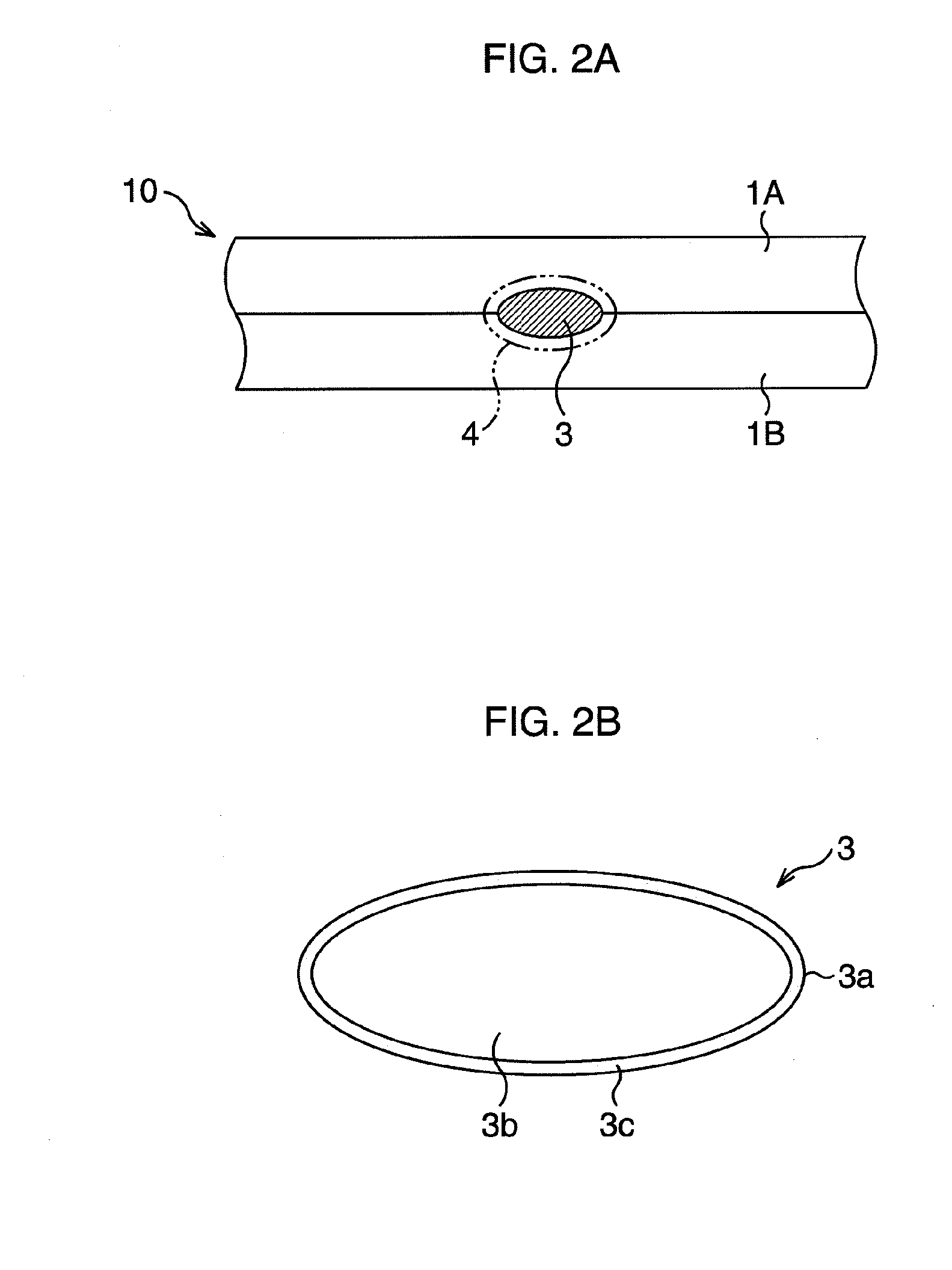
[0134]First, a first embodiment of the present invention will be described. FIG. 2A is a schematic diagram illustrating a spot welded joint according to the first embodiment.

[0135]As illustrated in FIG. 2A, in a spot welded joint 10 according to the first embodiment, two thin steel plates 1A and 1B are joined by spot welding via a nugget 3. Further, a heat-affected zone 4 exists in a periphery of the nugget 3. A tensile strength of either one or both of the thin steel plates 1A and 1B is 750 MPa to 1850 MPa, and a carbon equivalent Ceq thereof is equal to or more than 0.22 mass % to 0.55 mass %. Here, the carbon equivalent Ceq is represented by a formula (1).

Ceq=[C]+[Si] / 30+[Mn] / 20+2[P]+4[S]  (1)

[0136]([C], [Si], [Mn], [P], and [S] each represent respective contents (mass %) of C, Si, Mn, P, and S.)

[0137]Further, as illustrated in FIG. 2B, at least in a nugget outer layer zone 3c being a zone except a similar figure zone 3b which is 90% as large as an outer shape 3a of the nugget 3 ...

second embodiment

[0206]Next, a second embodiment of the present invention will be described. The second embodiment is a method for performing spot welding of the above-described steel plates 1A and 1B, and FIG. 3A to FIG. 3C are schematic diagrams illustrating a spot welding method according to the second embodiment.

[0207]In the second embodiment, first, as illustrated in FIG. 3A, two thin steel plates 1A, 1B being materials to be welded are overlapped each other. Then, while pressing welding electrodes 2A, 2B made of a copper alloy, for example, from both sides in relation to an overlapped portion of the thin steel plates 1A, 1B, that is, in a manner to sandwich from upper and lower directions in an example illustrated in FIG. 3A, predetermined energization is performed. The above energization includes welding energization and post-heating energization, details being described later. Then, as a result of such predetermined energization, a portion in which metal is melted is formed between the two t...

third embodiment

[0240]Next, a third embodiment will be described. In the third embodiment, except that welding energization is performed under a condition that a pressurizing force EF (N) of welding electrodes 2A and 2B against thin steel plates 1A and 1B fulfils a formula (7) below, similar processings as those of the second embodiment are performed.

1470×h≦EF1960×h  (7)

[0241]As described above, if the pressurizing force EF is less than “1960×h” (N), it becomes difficult to suppress an occurrence of a defect or a crack in a nugget 3, and thus when a thickness or strength of a steel plate increases, a defect or a crack sometimes occur. On the other hand, if the pressurizing force EF is less than “1960×h” (N), an effect that joint strength in a peel direction is increased prominently can be obtained. This is for the following reasons. In other words, as the pressurizing force EF is reduced, heat removal from welding electrodes 2A, 2B is reduced and penetration (a nugget thickness) is increased. Thus,...


PUM

PropertyMeasurementUnit
tensile strengthaaaaaaaaaa
grain diameteraaaaaaaaaa
tensile strengthaaaaaaaaaa

Abstract

Provided is a spot welded joint (10) which includes at least one thin steel plate with a tensile strength of 750 MPa to 1850 MPa and a carbon equivalent Ceq of equal to or more than 0.22 mass % to 0.55 mass % and in which a nugget (3) is formed in an interface of the thin steel plates (1A, 1B). In a nugget outer layer zone, a microstructure consists of a dendrite structure in which an average value of arm intervals is equal to or less than 12 μm, an average grain diameter of carbides contained in the microstructure is 5 nm to 100 nm, and a number density of carbides is equal to or more than 2×10⁶/mm2.

Description

TECHNICAL FIELD[0001]The present invention relates to a spot welded joint and a spot welding method of a high-strength steel plate used in an automobile field and the like.BACKGROUND ART[0002]In recent years, there is an increasing demand for using a high-strength steel plate for a vehicle body, a component, and so on in an automobile field. This is because weight saving of a vehicle body is necessary for achieving a fuel efficiency and a carbon dioxide gas (CO2) emission reduction and because collision safety should be improved. On the other hand, spot welding is mainly used in processes such as assembling of a vehicle body, mounting of a component, and the like. However, if a high-strength steel plate, in particular a high-strength steel plate whose tensile strength is high, is spot welded, following problems occur.[0003]As characteristics important in a joint which has been spot welded (hereinafter, referred to as a spot welded joint), a tensile strength and a fatigue strength ca...

Claims


Application Information

Patent Timeline
Patent Type & Authority Applications(United States)
IPC IPC(8): B32B15/01B23K11/16
CPCB23K11/115B23K11/166B23K2201/18B23K2201/34B23K2203/04Y10T428/12965C22C38/001C22C38/02C22C38/04C22C38/06B23K11/16B32B15/011B23K2101/18B23K2101/34B23K2103/04Y10T428/12347B23K11/11B23K31/00
Inventor OIKAWA, HATSUHIKOHAMATANI, HIDEKIAZUMA, MASAFUMISUZUKI, NORIYUKIWATANABE, FUMINORIMARUYAMA, NAOKIKAWATA, HIROYUKI
Owner NIPPON STEEL CORP
Why Eureka
Try Eureka