Underground Thermal Battery Storage System

a low temperature thermal storage and battery technology, applied in the field of underground low temperature thermal storage system, can solve the problems of energy loss, lack of thermal containment,

Inactive Publication Date: 2012-06-21
YATCHAK JOHN R
View PDF21 Cites 10 Cited by
  • Summary
  • Abstract
  • Description
  • Claims
  • Application Information

AI Technical Summary

Benefits of technology

[0006]The present invention describes a system to store thermal energy in an ‘underground thermal battery storage system’ structure. The ‘underground thermal battery storage system’ structure is comprised of one or more thermally insulated cell volumes where each cell volume contains a waterproof thermal insulation shell, one or more fluid storage tanks and surrounding earth matrix inside the thermal shell—which makes up the cell's thermal mass volume. A fluid thermal transport system with control valves and circulating pumps are used to thermally interconnect the fluid storage tanks and to transport the thermal e

Problems solved by technology

The lack of thermal containment is a major problem with underground thermal energy

Method used


Image

  • Underground Thermal Battery Storage System
  • Underground Thermal Battery Storage System
  • Underground Thermal Battery Storage System

Examples


Embodiment Construction

[0017]The embodiments described herein are examples of the use of the invention. The present invention is not limited to these embodiments but can be generalized to any process requiring the use of a low temperature ‘underground thermal battery storage system’.

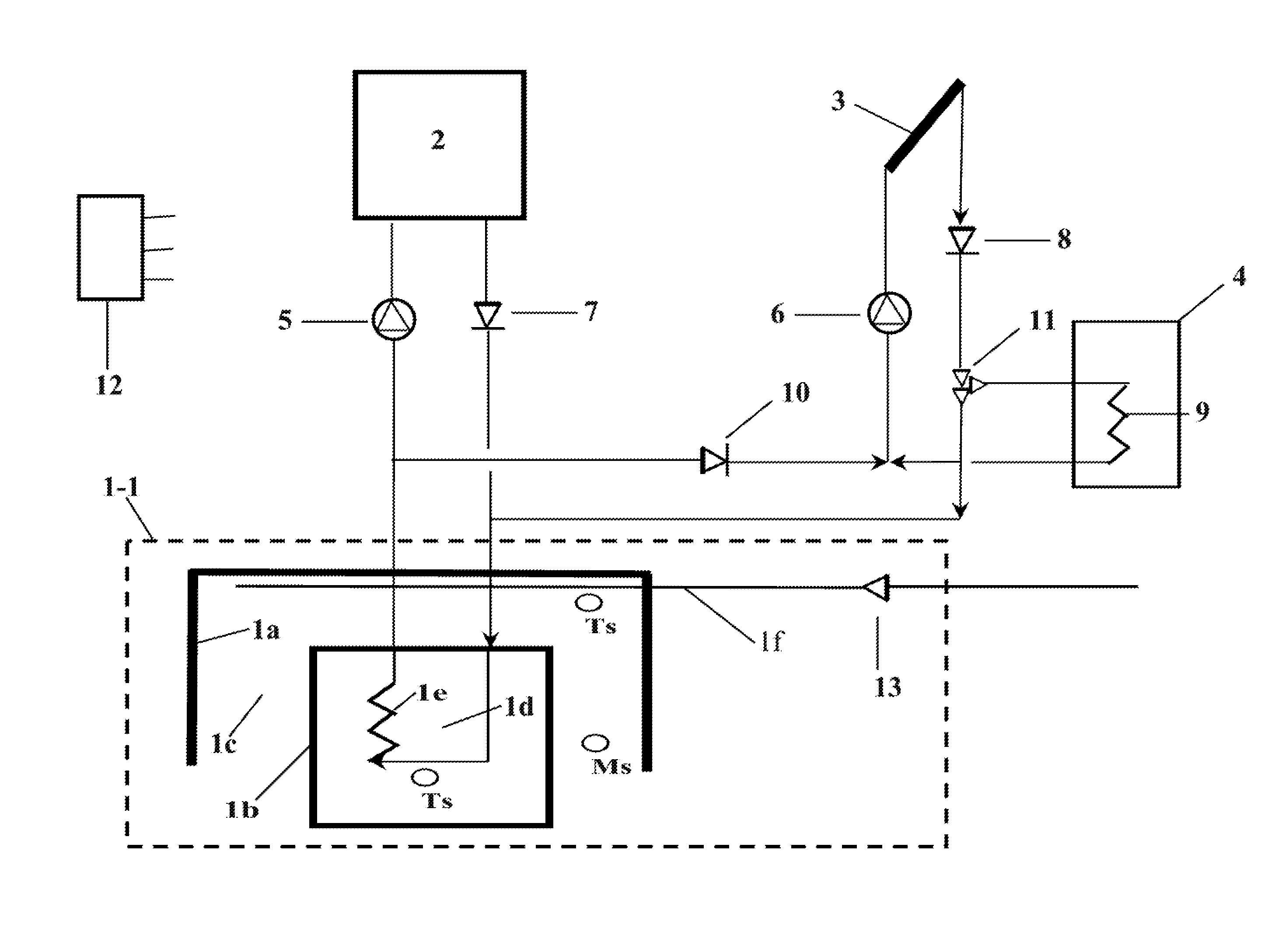
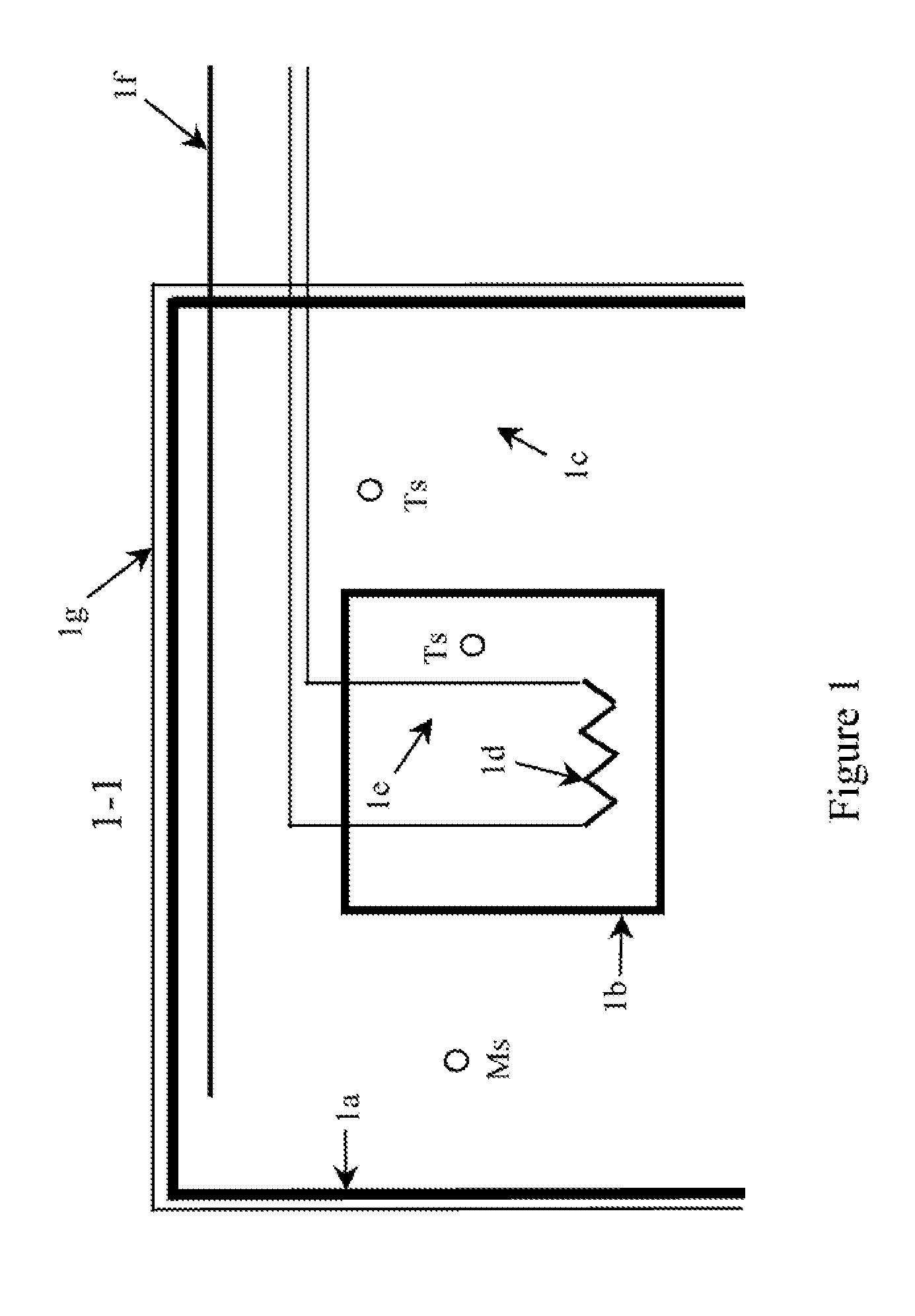
[0018]With reference to FIG. 1, which is a cross section of single tank—single cell volume embodiment of the ‘Underground Thermal Battery Storage System’. The thermal shield is shown 1a extending the vertical length, width, and height of the cell. The thermal shield consists of rigid insulating foam. The thickness of the foam can be varied to provide sufficient reductions in thermal loss for the desired operating range of the cells. The thermal shield can be buried at any depth but will normally be buried 1 meter or more consistent with the structural strength of the tank. The bottom surface of the shield will not normally be installed as it allows the cell to be buffered by the surrounding deep soil temperature. Omitting the ...


PUM


Abstract

‘Underground Thermal Battery Storage System’ using a battery structure of one or more underground thermally insulated cells, where each cell comprised of a waterproof thermal insulation shell, one or more fluid storage tanks and earth matrix. The thermal storage cell's fluid storage tanks are interconnected using a thermal fluid transport system with control valves, circulating pumps, and managed by a programmable controller. The programmable controller uses the cell sensors to determine cell status, control cell interconnections, and to manage the thermal charging and discharging by exterior heating or cooling devices. A moisture injection system is provided to control the thermal conductivity within the cell's earth matrix.

Description

CROSS REFERENCE TO RELATED APPLICATION[0001]This application claims benefit of Provisional Application ‘Earth Rechargeable Thermal Storage System—Thermal Battery’ dated May 15, 2010 with application number 61 / 345,095.FIELD OF INVENTION[0002]The present invention concerns an improved method for an underground low temperature thermal storage system using a battery cell concept where buried individually insulated thermal storage cells can be interconnected using a fluid transport system with control valves, circulating pumps, and a programmable controller, allowing the cells to dynamically serve as heat sources or sinks.[0003]Other's have recognized deficiencies in the current art for underground thermal energy storage system designs and have proposed various alternatives. In U.S. Pat. No. 4,361,135 Metz proposes an underground storage system beneath a home coupled to both a heat pump and using a solar array to charge the system. The underground storage system includes a octagonal tank...

Claims


Application Information

Patent Timeline
IPC IPC(8): F24J3/08F28D15/00
CPCF28D20/0043Y02E60/147F28D20/0052Y02E60/142F24D17/0021F24D19/106F24D2200/11F24D2200/12F24D2200/14F24D2220/08F24D17/02Y02B10/40Y02B10/20Y02B10/70F28F2270/00F28F13/00F28D2020/0082Y02E60/14
Inventor YATCHAK, JOHN R.
Owner YATCHAK JOHN R
Why Eureka
Try Eureka