Acoustic wave measuring apparatus, acoustic wave imaging apparatus and method for controlling acoustic wave measuring apparatus

a technology of acoustic wave measurement and imaging apparatus, which is applied in the direction of instruments, specific gravity measurement, applications, etc., can solve the problems of affecting the actual use of the laser, affecting the accuracy of the measurement, and the manufacture of the laser, etc., and achieves the effect of suppressing the cost of the apparatus and sufficient signal strength

Inactive Publication Date: 2012-07-05
CANON KK
View PDF14 Cites 29 Cited by
  • Summary
  • Abstract
  • Description
  • Claims
  • Application Information

AI Technical Summary

Benefits of technology

[0026]In the acoustic wave measuring apparatus according to the present invention, the measurement can be conducted with a sufficient signal strength while at the same time suppressing the apparatus cost.

Problems solved by technology

The actual use of these lasers, however, poses issues described below.
A first problem is the one of manufacture.
For this reason, the apparatus size and weight cannot be reduced easily, and the apparatus cost is increased.
Generally, however, the generation of the second harmonic from the fundamental wave produces a loss, and so does the generation of a laser light with a variable wavelength from the second harmonic.
To obtain the desired output, therefore, a very large output of the fundamental wave is required, which leads to an increased apparatus cost.
A second problem is a requirement to introduce an equipment to secure the safety of the laser.
The laser light has so high a linearity and a coherency that when the laser light erroneously enters an eye, for example, it may focus on the retina and reduce the visual acuity.
These factors restrict the introduction of the apparatus.

Method used


Image

  • Acoustic wave measuring apparatus, acoustic wave imaging apparatus and method for controlling acoustic wave measuring apparatus
  • Acoustic wave measuring apparatus, acoustic wave imaging apparatus and method for controlling acoustic wave measuring apparatus
  • Acoustic wave measuring apparatus, acoustic wave imaging apparatus and method for controlling acoustic wave measuring apparatus

Examples


first embodiment

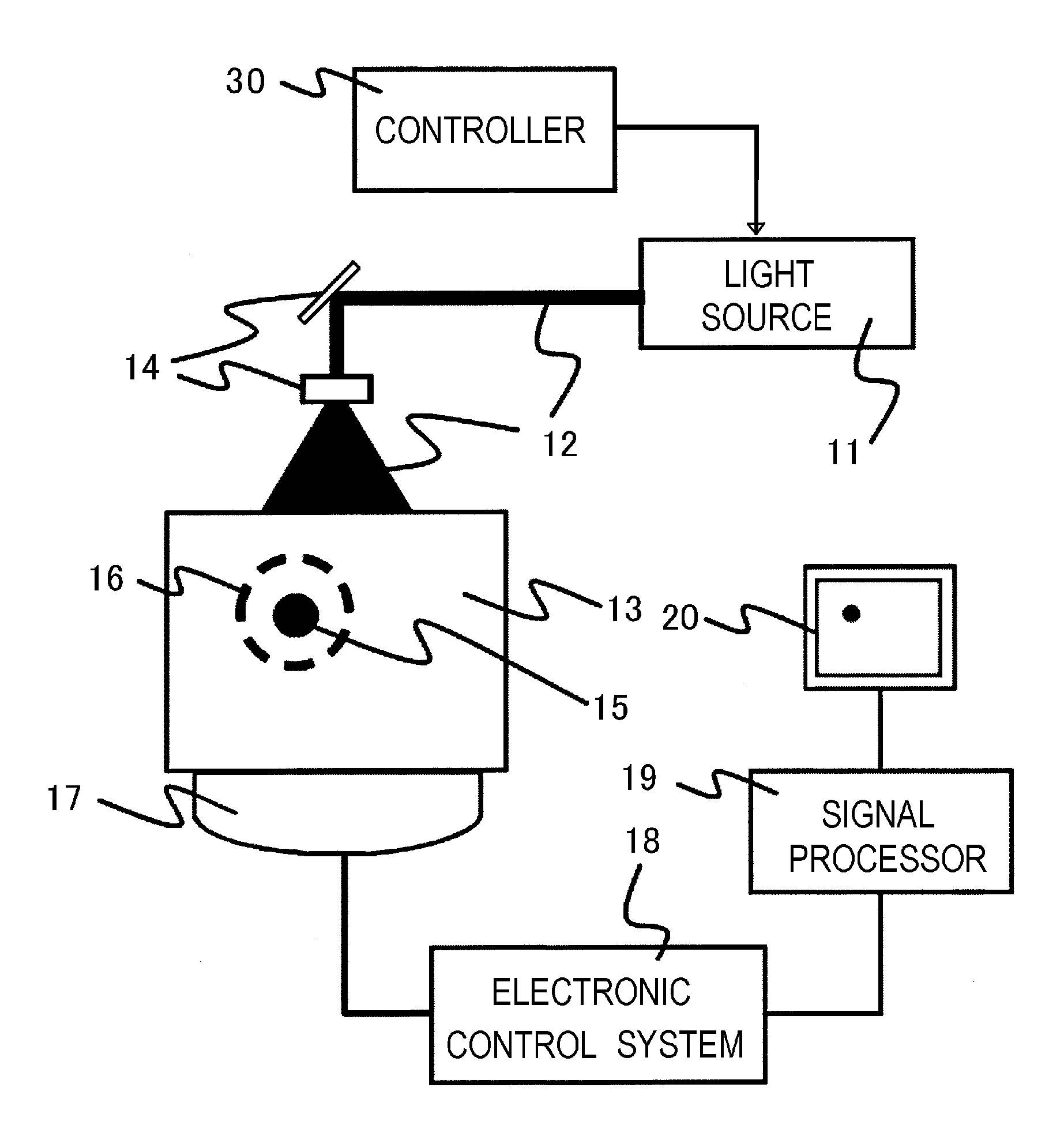
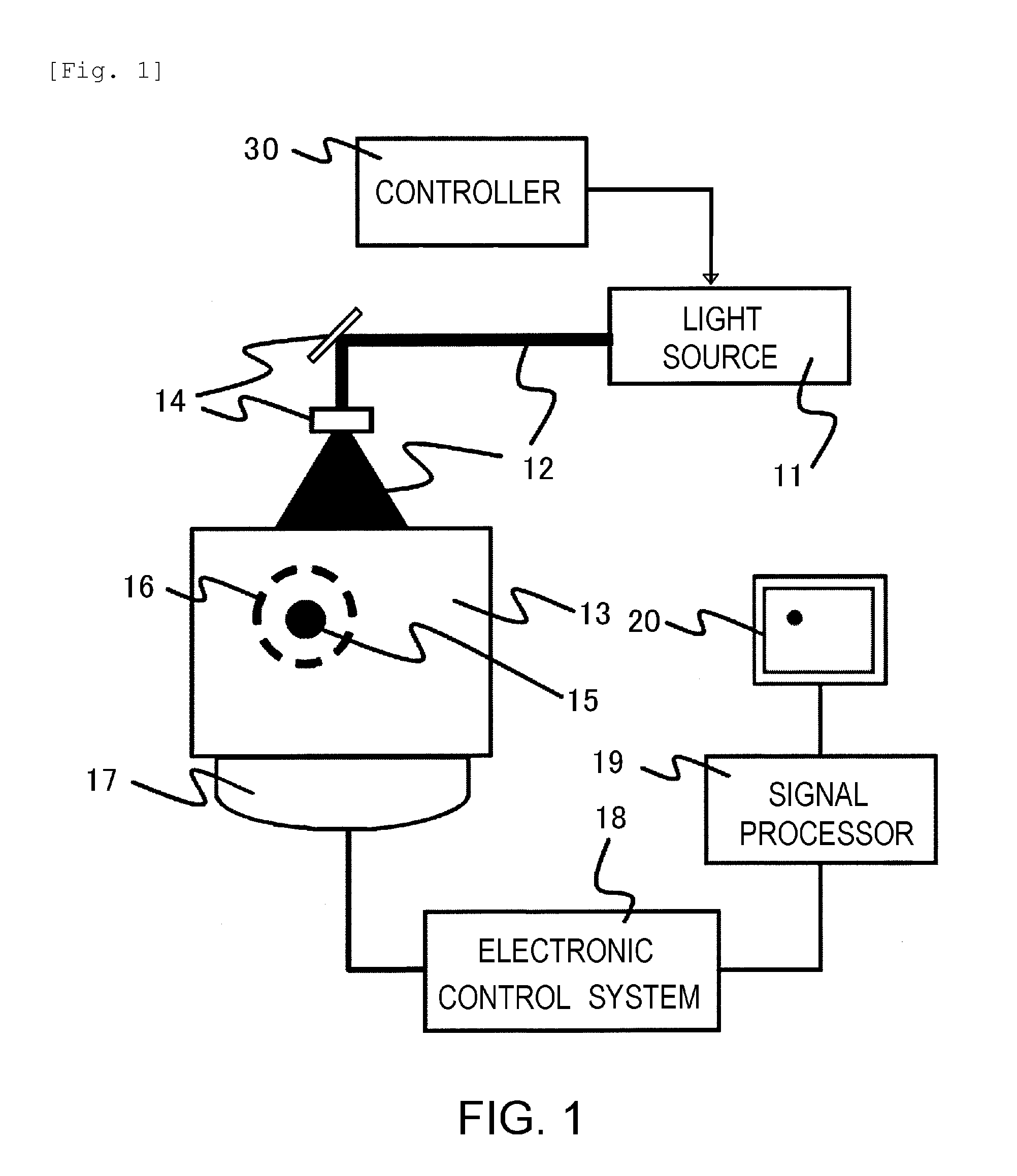
[0069]FIG. 1 shows the configuration of an acoustic wave measuring apparatus according to the present embodiment. This apparatus includes a light source11, an optical part 14, a detector 17, an electronic control system 18, a signal processor 19, an image display 20, and a controller 30.

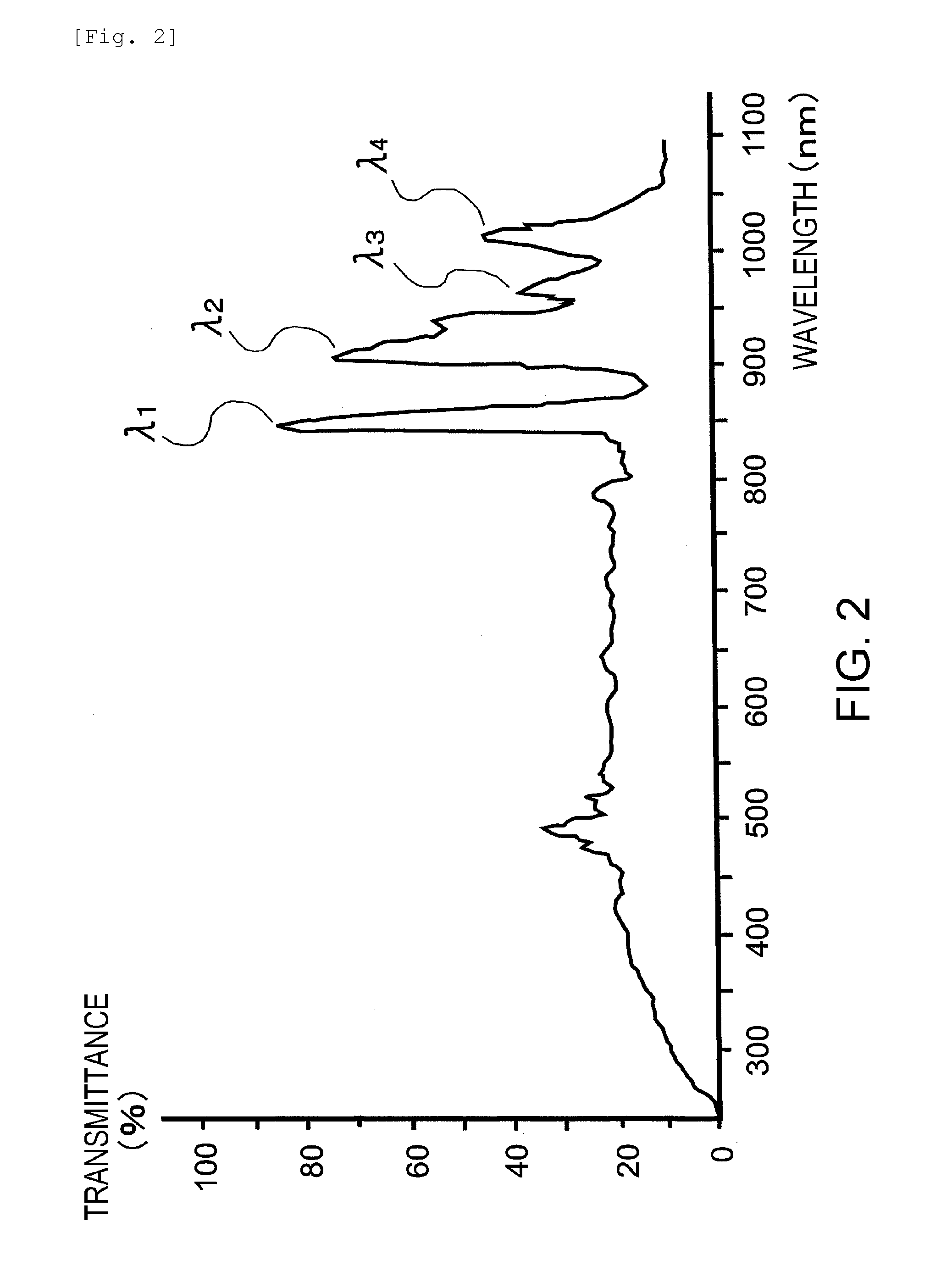
[0070]The light source 11 is an optical system configured of a xenon flash lamp and a plurality of light filters. The xenon flash lamp has the bright-line spectrum in the near-infrared area as shown in FIG. 2. The configuration of the light source and a method for controlling the light wavelength structure using the light filters are described in detail later.

[0071]The light source 11 radiates the light 12 on the subject 13. Though not shown, the light 12 can also be propagated using an optical waveguide such as an optical fiber. When the optical fiber is used, either the light of each light source can be introduced to the surface of the subject by using the optical fiber, or the light from a plurali...

second embodiment

[0090]The present embodiment is described with reference to a case in which the micro color filter system is used as a method for controlling the spectrum of the radiated light. FIG. 5 shows the manner in which the micro color filter is configured of a plurality of closely juxtaposing bandpass filters B1 to B4. Reference characters B1 to B4 designate the bandpass filters corresponding to the four wavelength peaks, respectively, of the xenon flash lamp. The bandpass filters B1 to B4 transmit only the light in the wavelength area containing the corresponding peaks, respectively. Also, FIG. 6 shows the manner in which the micro color filter shown in FIG. 5 is used for the optical system. In FIG. 6, the light source is similar to that of the embodiment described above, and the second embodiment is different from the first embodiment in that the former has a light shutter 91 and a micro color filter 92.

[0091]The pixels of the micro color filter 91 are arranged at the same pitch as the pi...

third embodiment

[0095]In the present embodiment, a case is described in which a device of reflection type is used in a method for controlling the spectrum of the radiated light. FIG. 7 shows the configuration of the optical system according to the present embodiment. Alight source portion and a micro color filter 102 have the same configuration as those in the embodiments described above.

[0096]A reflection-type device 101 reflects the light from the light source and guides it to the micro color filter. In the process, reflection or non-reflection of the light can be controlled in accordance with the pixel pitch of the bandpass filter. As a result, the spectrum of the radiated light can be controlled.

[0097]Like in the second embodiment, the liquid crystal panel can be used as the reflection-type device. From the viewpoint of the reflectivity, however, it is not preferable not to use a polarization plate. Instead, a digital mirror device (DMD) is a preferable choice. A multiplicity of micro mirrors i...


PUM


Abstract

An acoustic wave measuring apparatus includes a light source for radiating a light having a wavelength component in wavelength areas, light filters arranged in a light path from the light source to a subject and each to shut off or transmit the light in one of the wavelength areas, a detector for detecting an acoustic wave generated by the radiation, a controller for generating conditions having different combinations of the wavelength components contained in the light, and a signal processor for calculating an optical absorption coefficient of the subject for the light in each wavelength area based on a pressure of the acoustic wave detected under each of the conditions and a strength of the radiated light for each wavelength area under conditions.

Description

TECHNICAL FIELD[0001]The present invention relates to an acoustic wave measuring apparatus, an acoustic wave imaging apparatus and a method for controlling the acoustic wave measuring apparatus.BACKGROUND ART[0002]Generally, the imaging apparatuses using X rays, ultrasonic waves and MRI (magnetic resonance imaging) find wide application in the medical field. Also, in the medical field, the vigorous research effort is promoted on the optical imaging apparatus in which the light radiated on a living organism from a light source of a laser, etc. is propagated through a subject such as an organism, and by detecting this propagated light, the information inside the organism is obtained. An example of this optical imaging technique is photoacoustic tomography (PAT).[0003]The PAT is a technique for visualizing the information related to the optical characteristic values inside a subject (See PTL 1: U.S. Pat. No. 5,713,356). Specifically, upon radiation of the pulse light on a subject from ...

Claims


Application Information

Patent Timeline
Patent Type & Authority Applications(United States)
IPC IPC(8): G01H9/00
CPCA61B5/0059A61B5/0097G01N2021/1706G01N29/2418G01N21/1702
Inventor ASAO, YASUFUMI
Owner CANON KK
Why Eureka
Try Eureka