[0015]The particular geometry of the composite tube can be made in an
infinite number of shapes based on the ability to knit tubular sections in desired shapes. Not only can the
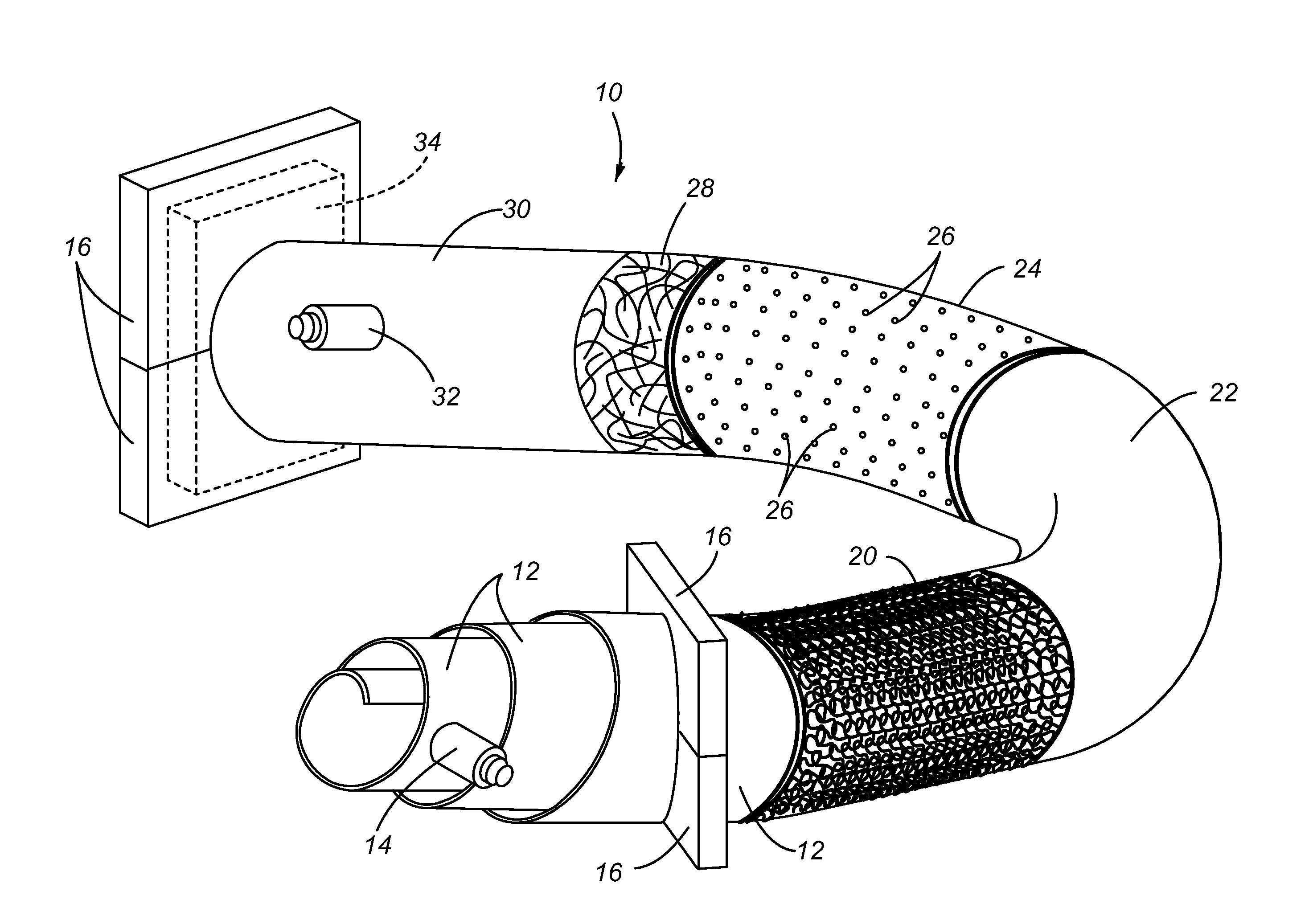
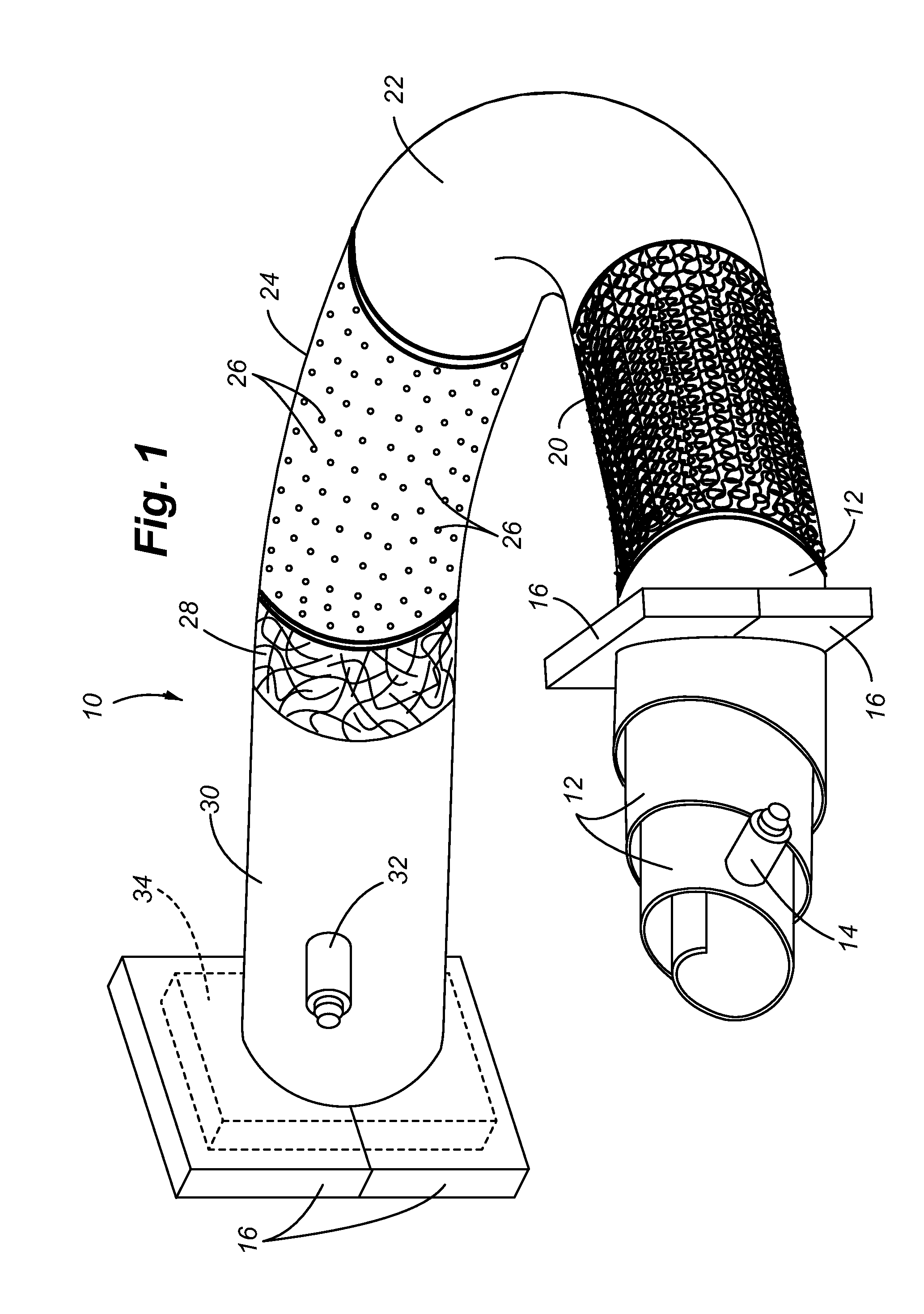
diameter of the tube be changed, but also turns or bends and other features can be created. Intersecting sections of tubes can be attached by stitching the abutting faces to one another. Thus, the knitted pattern of fibers can be considered a continuous integral support structure which eliminates the requirement for overlapping sections at tube intersection points, thereby avoiding delamination between the
layers of material.
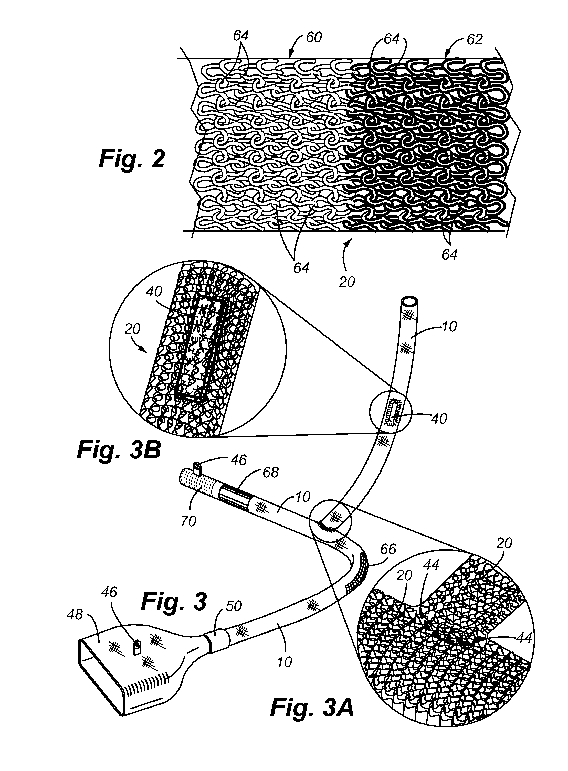
[0017]The use of a conventional circular knitting
machine such as used for fabrics is capable of creating the tubular arrangement of fiber in the present invention. The fiber may include materials such as
Kevlar®, carbon fiber, glass, and combinations thereof. The tubular knitted pattern provides for variable electrical, mechanical, and geometrical options that are difficult if not impossible to achieve with conventional composite tube manufacturing processes.
[0018]Once the knitted pattern is completed, the composite tube is then formed by a vacuum bag molding process. In general, a vacuum bag molding process involves a two sided mold that shapes both the internal and external surfaces of an object. Typically, the interior mold or mandrel is rigid, and the exterior mold is a flexible membrane or vacuum bag. In the present invention, in lieu of a rigid inner core or mandrel, an
inflatable bladder is placed within the knitted pattern to create
internal pressure. Preferably, the
inflatable bladder is provided in a twisted,
helical pattern that ensures the inflatable bladder is capable of applying even
internal pressure against the knitted pattern that may have various turns or changes in
diameter. The twisted
helical pattern enables the bladder to be inflated beyond just a cylindrical shape. The bladder has excess material that can fill larger spaces or may easily fit within smaller areas thereby accommodating different shaped tubes to be formed. Once the inflatable tube is in place, a
polymeric matrix is applied over the knitted pattern. The matrix material flows between the gaps in the knitted pattern and the matrix material is provided in sufficient quantity to create a desired thickness based on tube specifications. Preferably, the matrix material is the combination of a composite resin and
epoxy formulated with the desired properties for the particular tube application.
[0022]As mentioned with respect to the integral or one piece fiber knitted pattern, delamination is avoided at tube intersection points or other areas where separate tube sections are joined since the matrix material can be applied continuously across these intersection points. A continuously extending tubular fiber in combination with the continuously applied matrix material avoids all laminated seams or overlapping areas.
[0023]It is well known that most composite tubes are formed on rigid inner mandrels having limited flexibility. This reduces the available geometries for a tube to be formed because ultimately, the mandrel must be removed from the interior of the tube section. In the present invention, the shape holding feature of a tube design is built into the underlying fiber pattern itself. This method therefore allows for use of a very flexible and collapsible inner mold such as the inflatable bladder. Nevertheless, a vacuum bag molding technique can be used for necessary internal and external compressed molding, while critical exterior features and varied end configurations can be held in place by modular exterior fixturing. The manufacturing method of the invention therefore allows for extreme variability in creating tube intersections, small turn radii, varied diameters, varied shapes, and also contributes to very low tooling costs. Further, this manufacturing method allows for the construction of very long
pipe runs that traditionally require many laminated seams or junctions attached by couplers. The manufacturing method also allows for electronic integration of various monitoring sensors or heating elements to control temperatures, for example to comply with anti-
icing requirements for aircraft. The composite tube of the present invention provides many material advantages to include a non-metallic, a seamless composite that can be formed into an
infinite number of rigid shapes, and the composite tube is tunable for fine / incremental variations of electrical and mechanical properties.

