

Substrate for light-emitting element and light-emitting device
a technology of light-emitting elements and substrates, which is applied in the direction of lighting support devices, semiconductor/solid-state device details, lighting and heating apparatus, etc., can solve the problems of insufficient emission brightness, high cost of raw materials, and insufficient thermal conductivity of alumina substrates, etc., to suppress the tilt of the light-emitting element, improve the planarity of the mounting surface, and reduce the cost of raw materials. cost
- Summary
- Abstract
- Description
- Claims
- Application Information
AI Technical Summary
Benefits of technology
Problems solved by technology
Method used
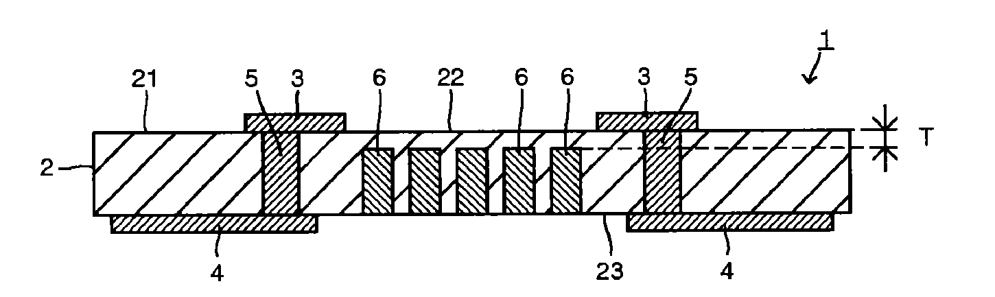
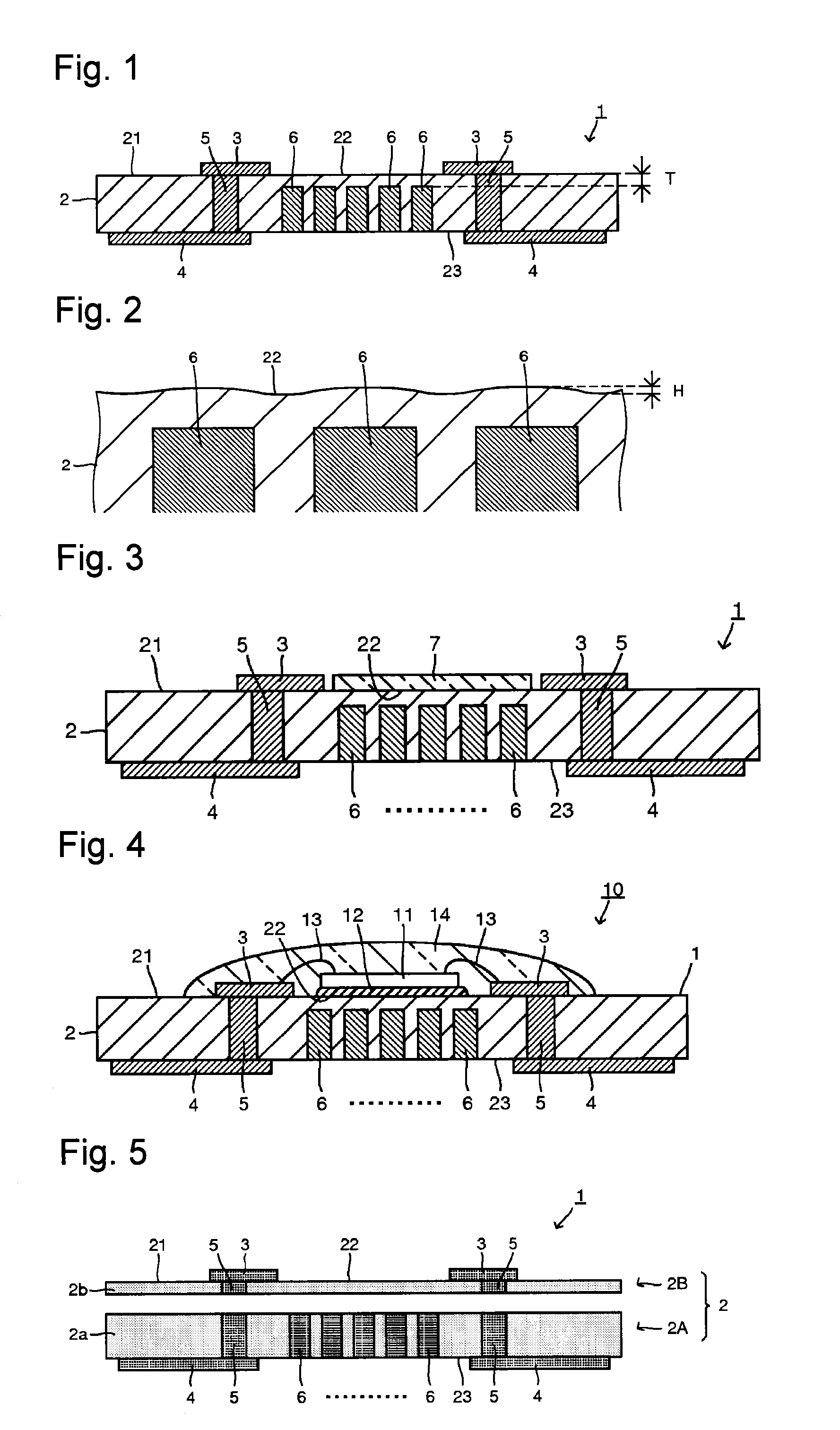
Image

Examples
examples
[0066]Now, the present invention will be described in detail with reference to Examples. However, it should be understood that the present invention is by no means restricted to such Examples.
examples 1 to 9
[0067]Firstly, a green sheet for main body and a green sheet for cover were prepared. That is, raw materials were blended and mixed so that SiO2 became 60.4 mol %, B2O3 15.6 mol %, Al2O3 6 mol %, CaO 15 mol %, K2O 1 mol % and Na2O 2 mol %, and this raw material mixture was put into a platinum crucible and melted at 1,600° C. for 60 minutes. Then, this molten state glass was cast and cooled. This glass was ground by a ball mill made of alumina for 40 hours to obtain a glass powder for the substrate main body. Here, ethyl alcohol was used as the solvent at the time of grinding.
[0068]40 mass % of this glass powder for substrate main body and 60 mass % of an alumina filler (tradename: AL-45H manufactured by Showa Denko K.K.) were blended and mixed to prepare a glass ceramics composition. To 50 g of this glass ceramics composition, 15 g of an organic solvent (a mixture of toluene, xylene, 2-propanol and 2-butanol in a mass ratio of 4:2:2:1), 2.5 g of a plasticizer (di-2-ethylhexyl phthal...
example 10
[0073]Example 10 is an example in which a mixture of a ceramics filler, an alumina filler and a zirconia filler was used.
[0074]The same glass powder for substrate main body as in Examples 1 to 9 was used. 38 mass % of this glass powder for substrate main body, 38 mass % of an alumina filler (tradename: AL-45H manufactured by Showa Denko K.K.) and 24 mass % of zirconia filler (tradename: HSY-3F-J manufactured by Daiichi Kigenso Kagaku Kogyo Co., Ltd.) were blended and mixed for 1 hour by a ball-mill to prepare a glass ceramics composition. To 50 g of this glass ceramics composition, 15 g of an organic solvent (a mixture of toluene, xylene, 2-propanol and 2-butanol in a mass ratio of 4:2:2:1), 2.5 g of a plasticizer (di-2-ethylhexyl phthalate), 5 g of polyvinyl butyral (tradename: PVK #3000K manufactured by DENKI KAGAKU KOGYO KABUSHIKI KAISHA) as a binder and 0.5 g of a dispersing agent (tradename: BYK180 manufactured by BYK Japan K.K.) were blended and mixed for 1 hour by a ball-mill...
PUM
| Property | Measurement | Unit |
|---|---|---|
| distance | aaaaa | aaaaa |
| distance | aaaaa | aaaaa |
| height | aaaaa | aaaaa |
Abstract
Description
Claims
Application Information