Temperature compensation and coarse tune bank switches in a low phase noise vco

a coarse tune and voltage compensation technology, applied in the field of varactor circuits, can solve the problems of affecting the varactor, increasing the vco phase noise in an undesirable way, affecting the voltage response of the varactor, and the transistor may break down and fail, so as to reduce the vco susceptibility, minimize the common mode noise across the two varactor circuits, and improve the vco phase noise

Active Publication Date: 2012-09-06
QUALCOMM INC
View PDF11 Cites 16 Cited by
  • Summary
  • Abstract
  • Description
  • Claims
  • Application Information

AI Technical Summary

Benefits of technology

[0011]In a first aspect, an LC tank of a Voltage-Controlled Oscillator (VCO) includes a main varactor circuit and temperature compensation varactor circuit coupled in parallel with the main varactor circuit. The main varactor circuit is used for fine tuning the VCO. The temperature compensation varactor circuit has a capacitance-voltage characteristic that differs from a capacitance-voltage characteristic of the main varactor circuit such that the effects of common mode noise across the two varactor circuits are minimized. In a first example, the temperature compensation varactor circuit has a capacitance-voltage characteristic of opposite slope to the slope of a capacitance-voltage characteristic of the main varactor circuit. The temperature compensation varactor circuit is made to have the capacitance-voltage charact...

Problems solved by technology

Noise from these sources affects the varactors and increases VCO phase noise in an undesirable way.
If a simple thin oxide transistor of such a semiconductor process were used for switch 21, then the transistor may break down and fail.
The parasitic capacitances of all of the many transistors of the switchable capacitor circuits, however, may combine to be...

Method used


Image

  • Temperature compensation and coarse tune bank switches in a low phase noise vco
  • Temperature compensation and coarse tune bank switches in a low phase noise vco
  • Temperature compensation and coarse tune bank switches in a low phase noise vco

Examples


Embodiment Construction

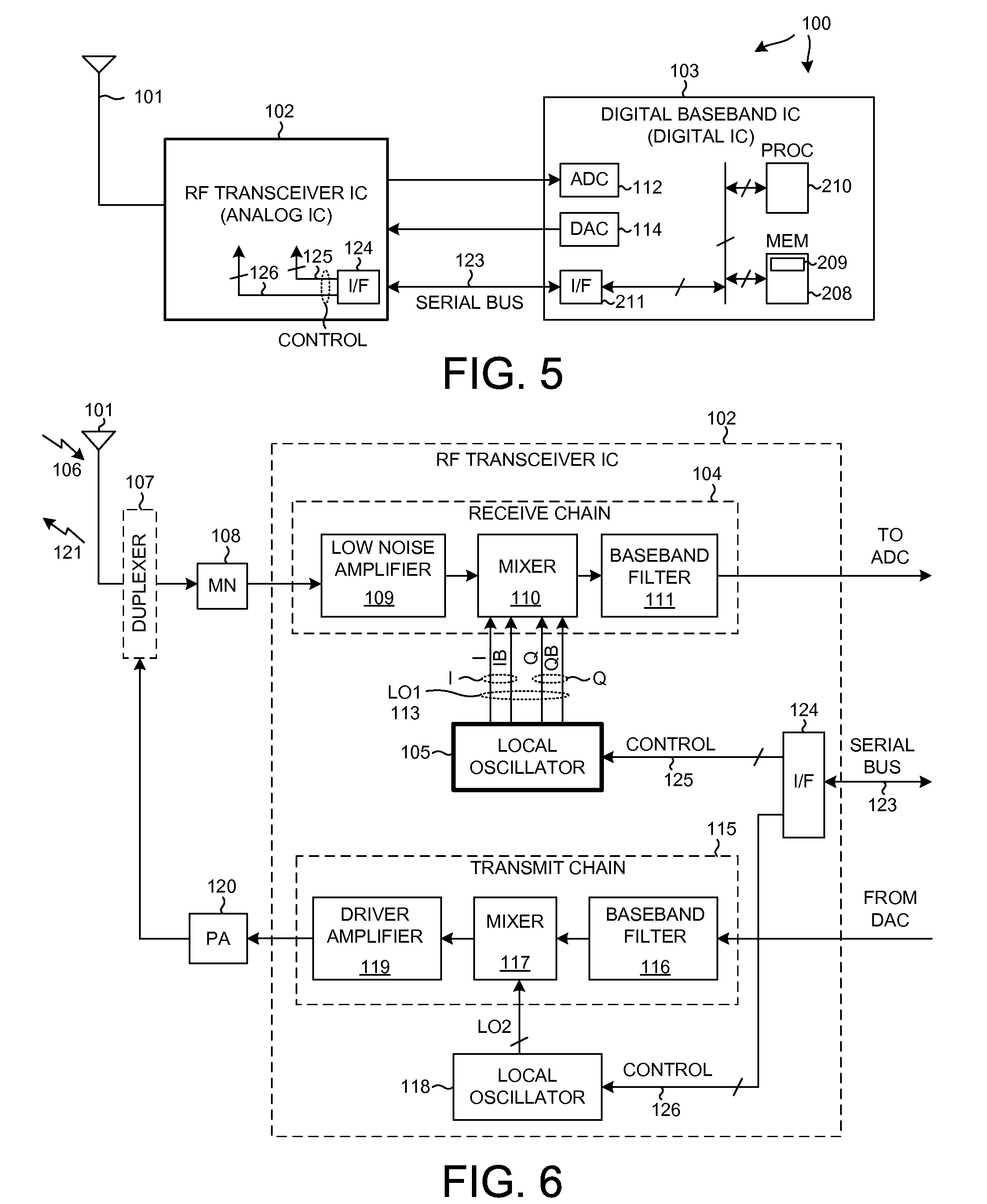
[0039]FIG. 5 is a simplified high level block diagram of a mobile communication device 100 in accordance with a first novel aspect. In this example, mobile communication device 100 is a cellular telephone. The cellular telephone 100 includes (among several other components not illustrated) an antenna 101 and two integrated circuits 102 and 103. Integrated circuit 103 is called a “digital baseband integrated circuit.” Integrated circuit 102 is a Radio Frequency (RF) transceiver integrated circuit. RF transceiver integrated circuit 102 is called a “transceiver” because it includes a transmitter as well as a receiver.

[0040]FIG. 6 is a more detailed block diagram of the RF transceiver integrated circuit 102 of FIG. 5. The receiver includes what is called a “receive chain”104 as well as a local oscillator 105. When the cellular telephone is receiving, a high frequency RF signal 106 is received on antenna 101. Information from signal 106 passes through duplexer 107, matching network 108, ...


PUM


Abstract

The LC tank of a VCO includes a main varactor circuit and temperature compensation varactor circuit coupled in parallel with the main varactor circuit. The main varactor is used for fine tuning. The temperature compensation varactor circuit has a capacitance-voltage characteristic that differs from a capacitance-voltage characteristic of the main varactor circuit such that the effects of common mode noise across the two varactor circuits are minimized. The LC tank also has a plurality of switchable capacitor circuits provided for coarse tuning. To prevent breakdown of the main thin oxide switch in each of the switchable capacitor circuits, each switchable capacitor circuit has a capacitive voltage divider circuit that reduces the voltage across the main thin oxide switch when the main switch is off.

Description

BACKGROUND INFORMATION[0001]1. Technical Field[0002]The disclosed embodiments relate generally to varactor circuits for fine tuning and / or to switchable capacitor circuits for coarse tuning in Voltage-Controlled Oscillators (VCOs).[0003]2. Background Information[0004]FIG. 1 (Prior Art) is a symbol of a Voltage Controlled Oscillator (VCO) 1. FIG. 2 (Prior Art) is a more detailed diagram of the VCO 1 of FIG. 1. VCO 1 includes an LC tank 2. The natural resonant frequency of the LC tank 2 largely determines the oscillating frequency of the differential VCO output signal output by the VCO 1 onto differential output conductors 3 and 4. In the illustrated example, the inductance of the LC tank 2 is provided by inductor 5. The capacitance of the LC tank 2 is provided by a combination of capacitance elements including a varactor circuit 6 and a coarse tune capacitor bank 7. The coarse tune capacitor bank 7 is made up of a number of parallel-connected switchable capacitor circuits. Reference ...

Claims


Application Information

Patent Timeline
IPC IPC(8): H01L29/93
CPCH03L1/02H03L7/104H03L7/099H03L7/10
Inventor ZHANG, GANG
Owner QUALCOMM INC
Why Eureka
Try Eureka