

Composite Building Panel and Method
- Summary
- Abstract
- Description
- Claims
- Application Information
AI Technical Summary
Benefits of technology
Problems solved by technology
Method used
Image

Examples
Embodiment Construction
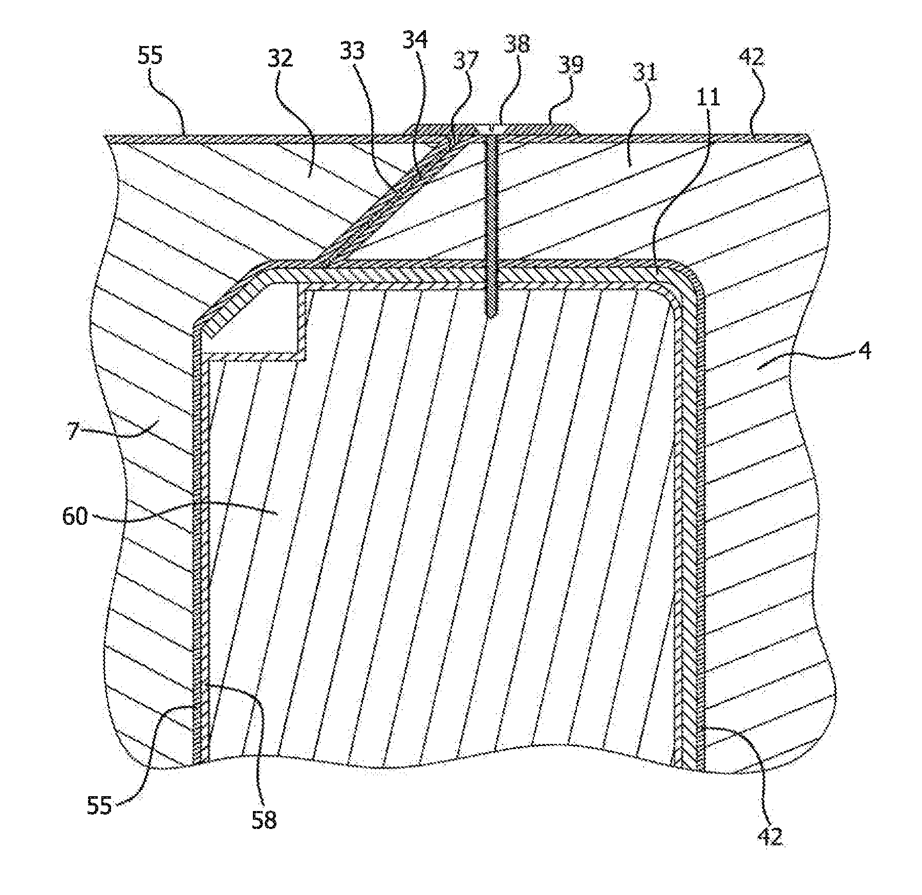
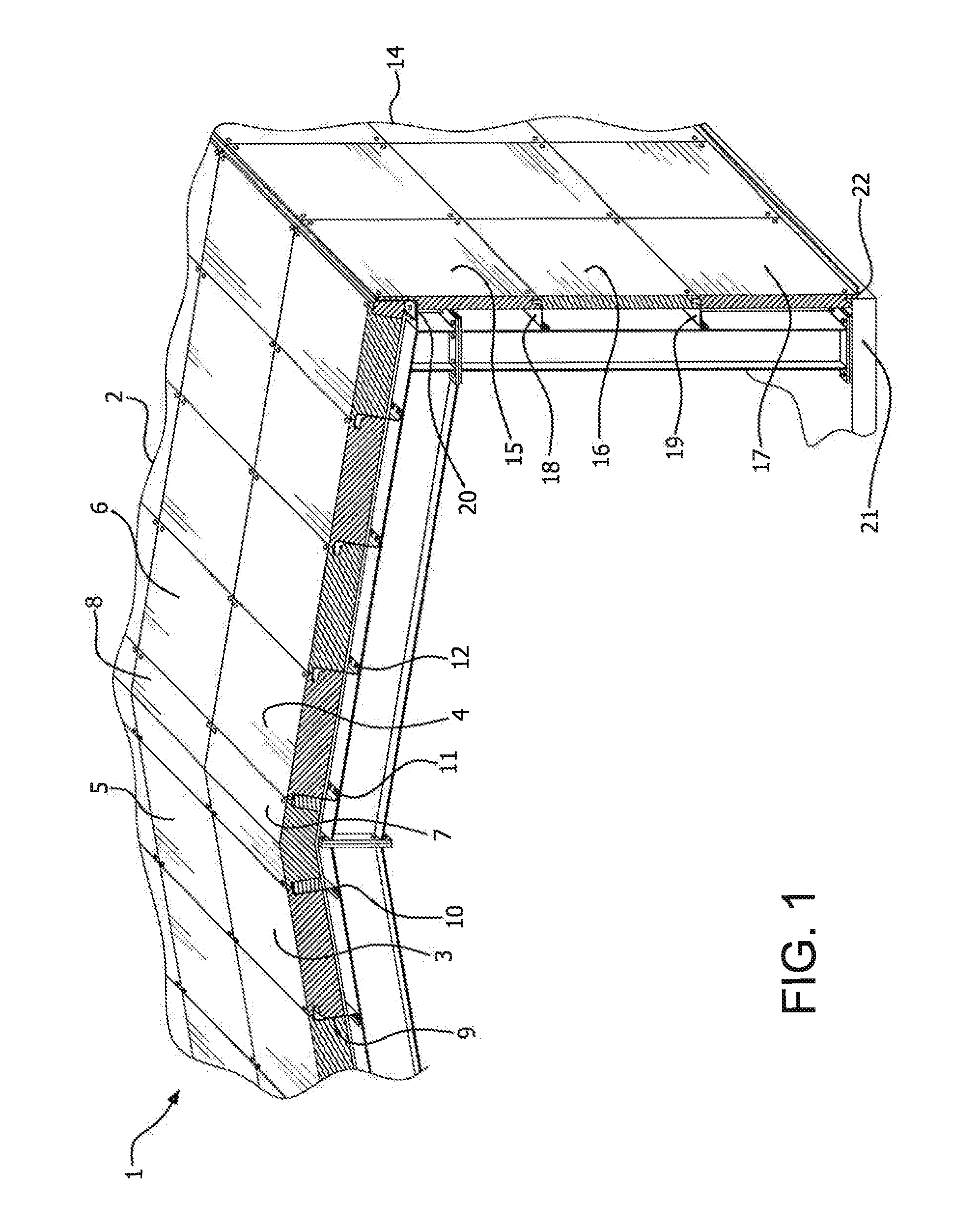
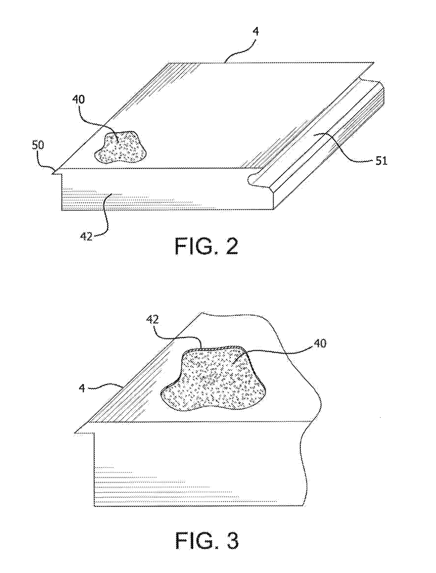
[0034]The components of roof and exterior wall construction system 1 of the present invention are most clearly shown in FIG. 1, a partial cross-sectional representation of a roof construction unit and attached exterior wall construction unit of a building. Roof construction unit 2 comprises a plurality of foam encapsulated roof panels adjacently aligned. Roof panels 3, 4, 5 and 6 are referenced in FIG. 1, which also shows additional roof panels which comprise roof construction unit 2. Roof panels 7 and 8 are roof peak panels. Each panel is fitted between roof purlins or like support members, e.g. 9, 10, 11, and 12 which extend substantially the length of roof construction unit 2. Each roof panel, including the roof peak panels, is custom designed and manufactured to be fitted within an adjacent purlin and compressed together and pressure-fitted against adjacent panels and purlins to form uniform roof construction unit 2.
[0035]In like manner, exterior wall construction unit 14 compri...
PUM
| Property | Measurement | Unit |
|---|---|---|
| Fraction | aaaaa | aaaaa |
| Linear density | aaaaa | aaaaa |
| Tensile strength | aaaaa | aaaaa |
Abstract
Description
Claims
Application Information