Tri-barrier ceramic coating

a ceramic coating and tri-barrier technology, applied in the direction of blade accessories, climate sustainability, machines/engines, etc., can solve the problems of metallic coating oxidizing at a very fast rate, losing its load-carrying function, and insufficient protection of superalloy articles

Inactive Publication Date: 2012-11-01
CHROMALLOY GAS TURBINE
View PDF4 Cites 15 Cited by
  • Summary
  • Abstract
  • Description
  • Claims
  • Application Information

AI Technical Summary

Problems solved by technology

At the desired high temperature, the components in the hot engine section made of a Ni or Co based superalloy, even the advanced directionally solidified or single crystal nickel-based superalloys, will lose its load carrying function due to their mechanical strength being weakened due to overheating.
The most advanced metallic coatings such as a McrAlY or platinum aluminized coating, which are applied onto the Ni or Co based superalloy turbine blades and vanes, are not adequate in protecting the superalloy article from oxidation since at this elevated temperature the metallic coating will oxidize at a very fast rate.
In addition, these metallic coatings do not offer a sufficient thermal barrier to protect the superalloy article from overheating.
Observations and failure investigations of overhauled engine blades and vanes have demonstrated that the TBC deterioration is primarily caused by CMAS and erosion attack.
Once the TBC is removed locally or entirely by CMAS attack, the bond coat and base alloy are subjected to high temperature-induced deterioration.

Method used


Image

  • Tri-barrier ceramic coating
  • Tri-barrier ceramic coating
  • Tri-barrier ceramic coating

Examples


example

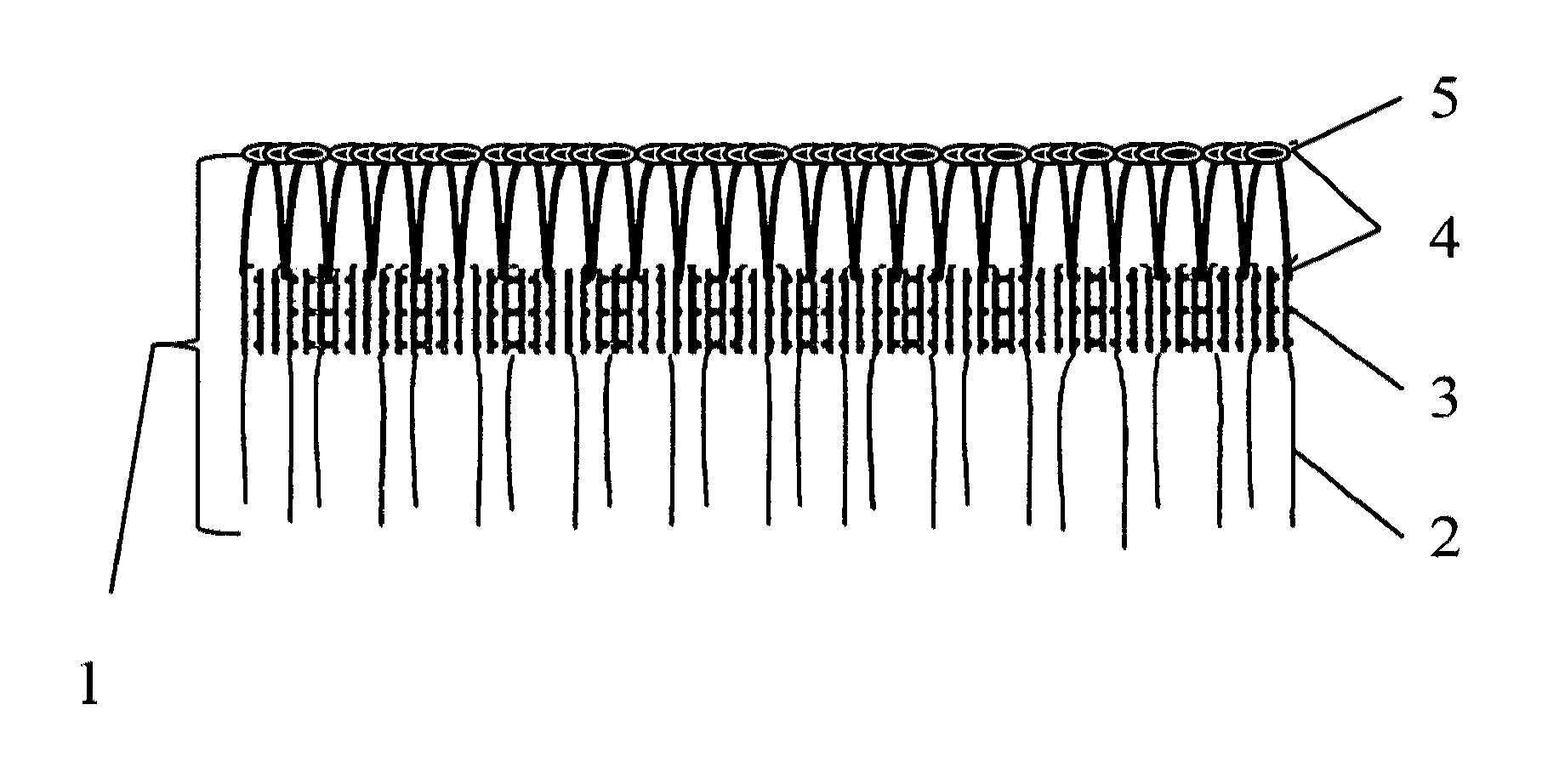
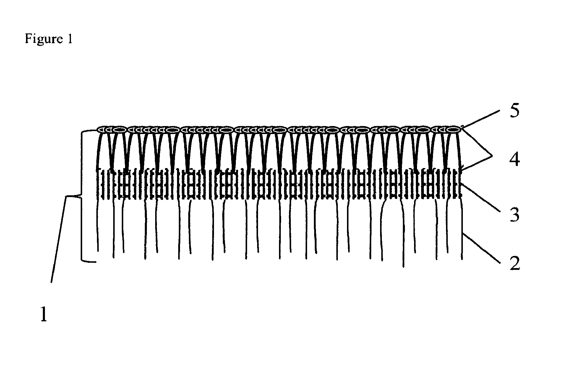
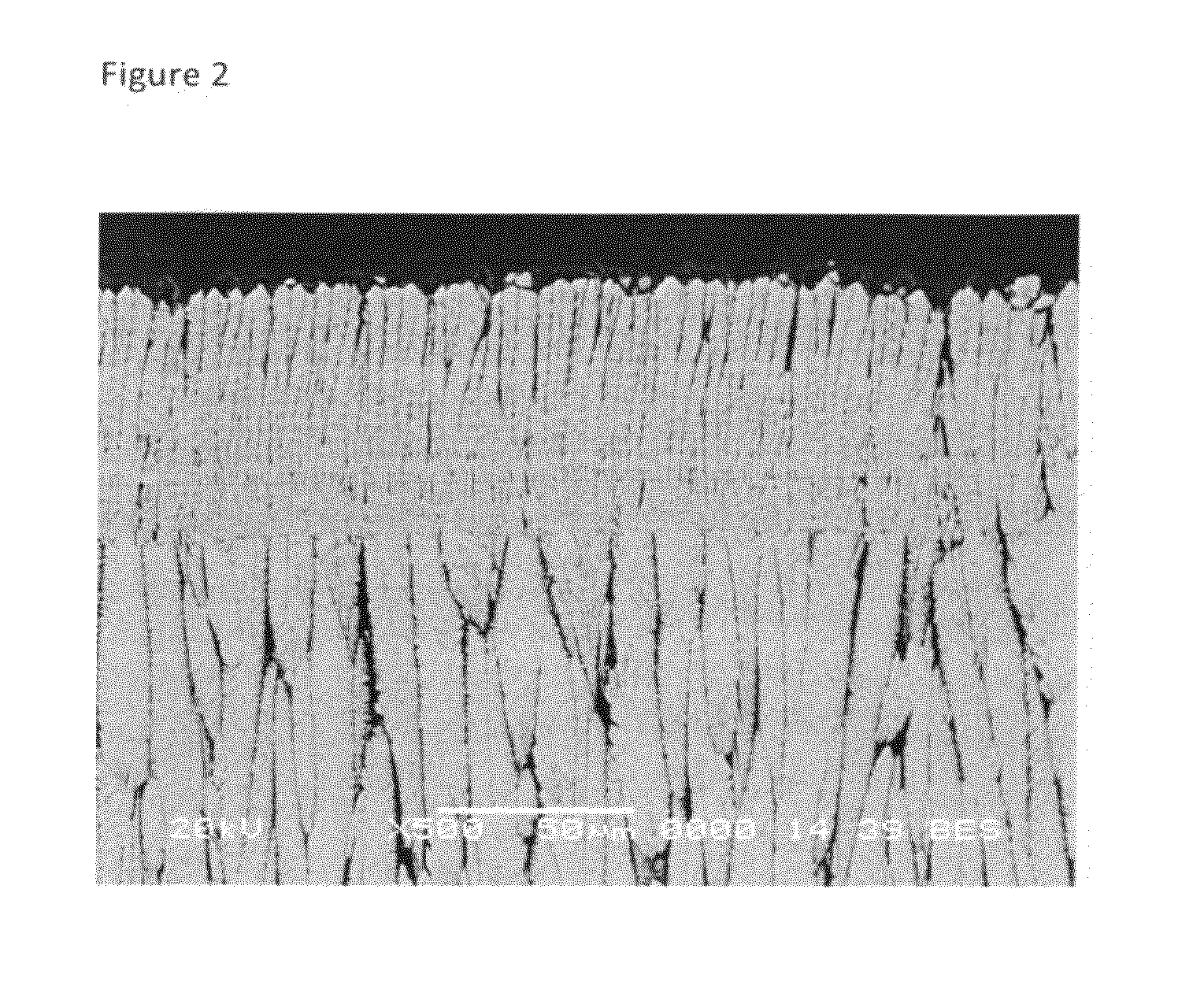
[0021]The tri-barrier coating was applied to nickel based super alloy surface as follows: a NiCoCrAIYHfSi bond coat was first applied to the alloy; a base thermal barrier layer of Nd0.1Zr0.9O1.95 with Y and Hf dissolved in (see U.S. Pat. No. 7,041,383) was applied to the bond coat surface by EBPVD with a rotation rate of 6 rpm and a gun power of 2.2 to 2.4 Amps (coating tank temperature of 1800° F.) creating a TBC layer 9 mils thick with a mean columnar width of 10 to 25 μm with gaps between the columns of 0.2 to 4 μm; the base thermal barrier layer was cooled to ambient temperature then polished to a surface roughness of Ra 30 mirco-inch; an intermediate CMAS barrier layer of Nd0.1Zr0.9O1.95 with Y2O3 and HfO2 dissolved in was applied to the surface of the base layer by EBPVD with a rotation rate of 2 rpm and a gun power of 1.8 Amps (coating tank temperature of 1600° F.) creating a TBC layer 1 mil thick with inter columnar nano pores on the top and a grid like structure on the bott...


PUM

PropertyMeasurementUnit
column widthaaaaaaaaaa

Abstract

A tri-barrier ceramic coating system is provided having a base thermal barrier layer, an intermediate CMAS barrier layer, and a top erosion barrier layer, and the method of applying such a coating system to a substrate. The base layer has a typical columnar structure with inter-columnar gaps and intra-columnar micro-pores that provides the stress tolerance during thermal cycles. The intermediate CMAS barrier layer has the fiber-like columns with inter-columnar nano-pores and a grid structure on the bottom of the layer. The fine structured intermediate layer covers the gaps between the columns of the base layer and will block CMAS infiltration effectively. The top erosion resistant layer contains wider TBC columns with narrow inter-columnar gaps and a modified cauliflower-like TBC head that provides erosion resistance for the underlying layers. The tri-barrier coating microstructure will further reduce the thermal conductivity as comparing to the conventional single layer system.

Description

FIELD OF THE INVENTION[0001]This invention relates to a thermal barrier coating for components that are exposed to the hostile gas turbine engine operation environment. More particularly, this invention relates to a thermal, CMAS and erosion tri-barrier ceramic coating system designed to protect turbine engine hot section components against CMAS and erosion attack, while having increased thermal protection. In addition, this invention provides a specific method of applying the tri-barrier coating system.BACKGROUND OF THE INVENTION[0002]In advanced turbine engines, combustion chamber temperatures may exceed 2400 degrees F. in order to increase the power output of the engine for high thrust and high efficiency. At the desired high temperature, the components in the hot engine section made of a Ni or Co based superalloy, even the advanced directionally solidified or single crystal nickel-based superalloys, will lose its load carrying function due to their mechanical strength being weak...

Claims


Application Information

Patent Timeline
Patent Type & Authority Applications(United States)
IPC IPC(8): B32B18/00C23C14/30B32B7/02
CPCC04B35/486C04B2235/3224C04B2235/3225C04B2235/79Y10T428/24967C23C14/24F01D5/288F01D5/284C23C14/083Y10T428/24355Y10T428/24997Y02T50/60
Inventor LIU, LUCY YOURONGLAWTON, PAULLAWTON, PATRICIA
Owner CHROMALLOY GAS TURBINE
Why Eureka
Try Eureka