
Dissection handpiece and method for reducing the appearance of cellulite

a cellulite and handpiece technology, applied in the field of surgery tools and implantable devices, can solve the problems of affecting the appearance of cellulite, and affecting the appearance of cellulite, and achieve the effect of increasing the fluid kinetic energy

Active Publication Date: 2012-11-01
ULTHERA INC
View PDF2 Cites 52 Cited by
  • Summary
  • Abstract
  • Description
  • Claims
  • Application Information

AI Technical Summary

Benefits of technology

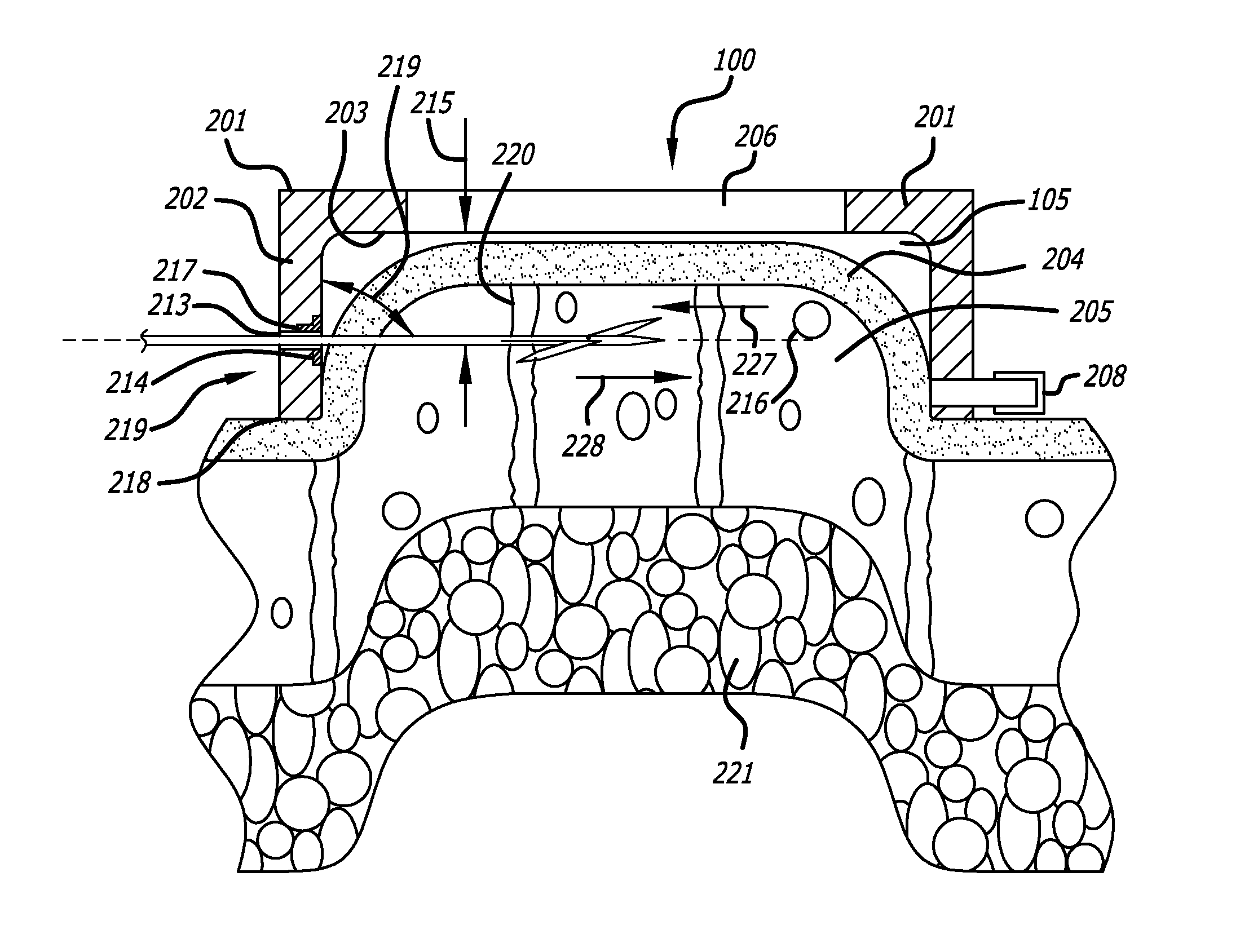
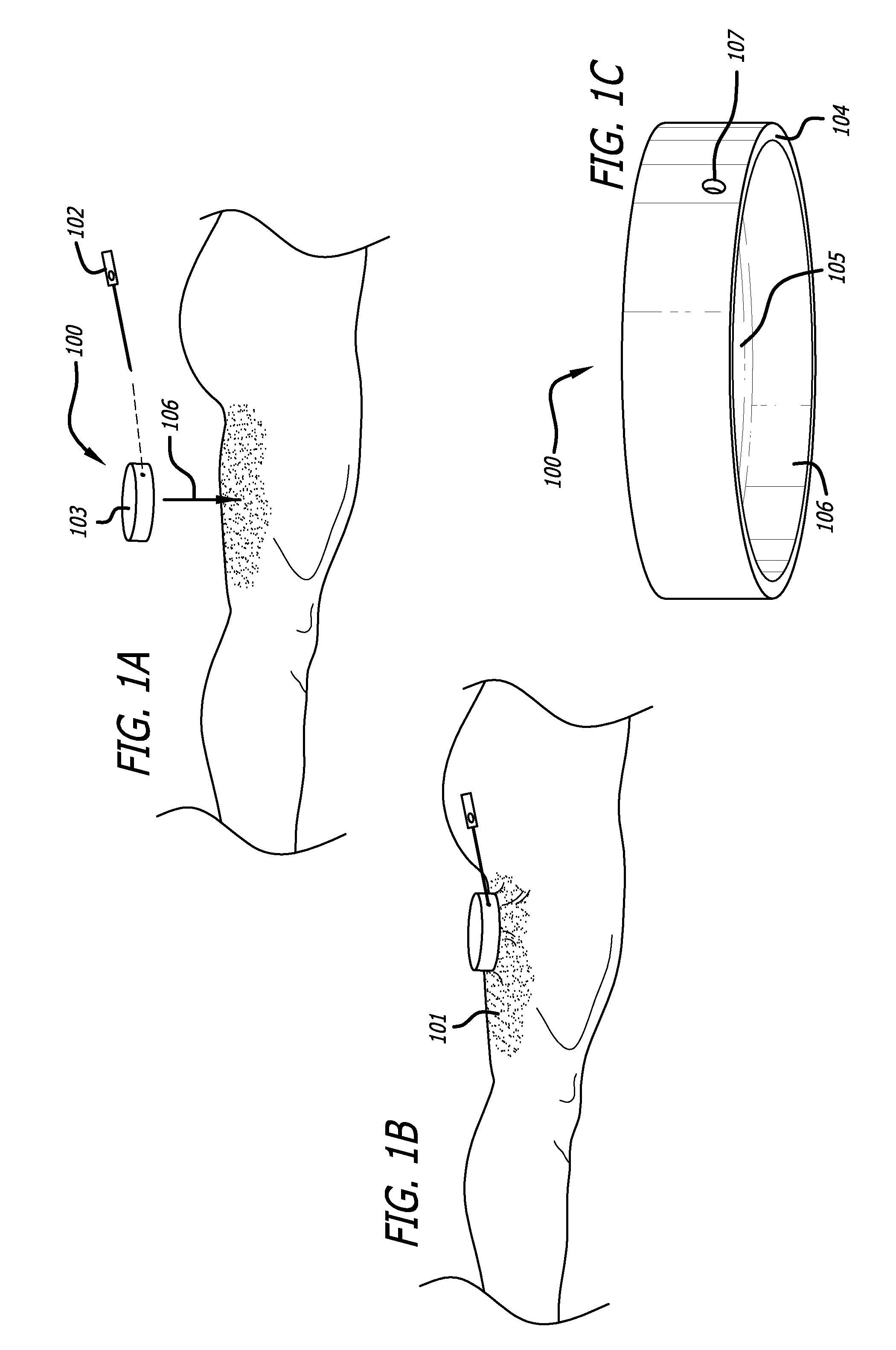
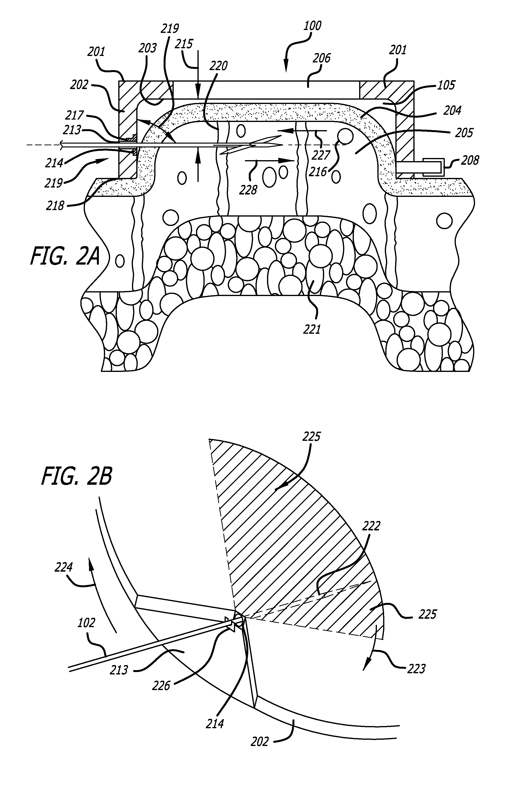
[0021]In some aspects, the tool comprises a cutting blade and a reciprocating motor coupled to the cutting blade, said reciprocating motor reciprocating the cutting blade. The tool may further include a sleeve, wherein the cutting blade is at least partially slidably disposed within the sleeve. The tool may also include an injection device and a nozzle, wherein the nozzle is configured to discharge a fluid in a direction parallel to the top of the handpiece and configured to increase a kinetic energy of the fluid when the fluid is injected by the injection device through the nozzle.
[0023]The device may also be configured to include an elastomeric septum, the elastomeric septum being configured to be pierced by the tool and to substantially self-seal when the tool is removed such as to substantially prevent a vacuum leakage from the recessed area when a vacuum is supplied to the recessed area. Other aspects may include the device comprising a support arm having a guide pin, the tool being mounted to the support arm, wherein the guidance track operably connected to the handpiece includes the guidance track being disposed on a surface of the top of the handpiece and slidably receiving the guide pin, the guidance track facilitating movement of the pin and support arm along the predetermined path.

Problems solved by technology

Furthermore, adipocyte expansion from weight gain may also stretch the septae.
This results in areas of the skin being held down while other sections bulge outward, resulting in the lumpy, ‘orange peel’ or ‘cottage cheese’ appearance on the skin surface.
Although a multitude of therapies exist, most of them do not provide a lasting effect on the skin irregularity, and some therapies may even cause the worsening of cellulite in certain patients.
Yet other treatments for cellulite have negative side effects that limit their adoption.
Regardless, most of these therapies require multiple treatments on an ongoing basis to maintain their effect at significant expense and with mixed results.
Such techniques may utilize a high intensity ultrasound wave that is focused on a tissue within the body, thereby causing a localized destruction or injury to cells.
Although low acoustic pressure ultrasound may somewhat heat tissue, the tissue is not heated sufficiently to cause direct tissue disruption or to enhance the ablation, and thus significantly reduces the risk of thermal damage to the dermis and associated structures (nerves, hair follicles, blood vessels).
There are physicians who target the more shallow subdermal fat pockets with liposuction, but at a higher risk of directly creating surface irregularities rather than treating them.
Liposuction is not considered a viable treatment for cellulite for these reasons.
Another issue that must be factored in with liposuction is the amount of drugs infused with the tumescent solution.
However, in some cases lidocaine can spill over into the circulation and has resulted in patient mortality.
For this reason, physicians monitor the Lidocaine does closely and often limit the area or treatment as a result.
While clinically effective in some patients, pain, bruising, bleeding and scarring can result.
Cutting or relieving of the fibrous septae in the subdermal region by current subcision methods, is labor intensive, time consuming and techniques are highly variable.
Significant physician time must be devoted to the procedure and there are technical limits as well as anesthetic limits to the size of a treatable area.
There is a lack of clinical proof of that the techniques work for most patients and that the effects are lasting.

Method used


Image

  • Dissection handpiece and method for reducing the appearance of cellulite
  • Dissection handpiece and method for reducing the appearance of cellulite
  • Dissection handpiece and method for reducing the appearance of cellulite

Examples


third embodiment

[0103]FIGS. 11A through 11D depict a yet further embodiment of the platform. In this embodiment, platform 309 of the previous embodiments is replaced by support arm 1101 movably coupled to handpiece 100. Support arm 1101 includes a guide pin 1102 which interacts with a guidance track 1103 defined in the top portion of the handpiece 100. A handle 1104 is used to advance support arm 1101 as guided by the interaction of the guide pin 1102 and guidance track 1103. Guide pin 1102 moves within and along guidance track 1103 to stabilize a cutter module 1105 at a proper position proximate to handpiece 100. Cutter module 1105 can be adapted to use any cutting mechanism disclosed herein. In one aspect cutter module 1105 may include cutting implement 102. In another aspect cutting module 1105 is manually controlled. In the depicted embodiment cutting module 1105 is motor controlled and includes a housing, a gear motor, cutting blade 1106, and sleeve 1107 similar to the embodiment depicted by F...

first embodiment

[0170]As shown by FIGS. 23A through 23E, the system may include a mesh deployment applicator 2301 to deploy a fibrous mesh 2302 through a single needle hole in a dermis to create a highly fibrous layer directly or through wound healing processes. The implantable mesh may be self-expandable, and is generally flat, flexible, and can recover its shape and most of its size after compression. In other embodiments mesh 2302 may be detachably coupled to a resiliently compressible self-expandable frame (not illustrated). In a first embodiment, implantable mesh 2302 is preferably disposed at or near a distal end 2303 of deployment applicator 2301. The applicator is inserted percutaneously through the skin using a subdermal catheter such as that described above, or by itself through a hole in the skin, to deploy the implantable mesh located at or near its distal end to a treatment area in the subdermal fat or in the layer between the subdermal fat and the skin. It should be noted that the mes...

second embodiment

[0178]FIGS. 24A through 24F depict a mesh deployment applicator. In this embodiment, a sheath 2305 may include or be interchangeable with an introducer needle 2401, and a guide wire may be omitted. A deployment shaft 2402 and keeper rod 2403 are disposed inside introducer needle 2401. Mesh 2404 is configured to be furled (i.e., rolled up) around shaft 2402 and keeper rod 2403. Introducer needle 2401 (with mesh inside) may then be inserted through an entry wound 2405 created by tool 102. After insertion, needle 2401 slides off over a proximal end 2406 of shaft 2402 and keeper rod 2403, leaving the furled mesh 2404 positioned with subcision region 2407. Shaft 2402 is simultaneously rotated about its longitudinal axis 2408 to un-furl mesh 2404, and pivoted about the skin-entry point 2405 to pull mesh 2404 across subcision region 2407. Keeper rod 2403 is maintained in a fixed position as mesh 2404 is un-furled, so as to anchor the edge of mesh 2404 at the desired location within subcisi...


PUM


Abstract

A dermatological skin treatment device is provided. The device comprises a handpiece and a cutting tool, wherein the tool is inserted through the conduit and percutaneously inserted into a tissue disposed within a recessed area of the handpiece. The device and method cut the fibrous structures under the skin that cause cellulite at an angle substantially parallel to the surface of the skin and replace these structures with a non-cellulite forming structure by deploying a highly fibrous mesh through a single needle hole to create a highly fibrous layer directly or through wound healing processes.

Description

CROSS-REFERENCES TO RELATED APPLICATIONS[0001]This application is a continuation-in-part and claims priority from U.S. application Ser. No. 12 / 555,746, filed Sep. 8, 2009, which is a continuation-in-part and claims priority from U.S. application Ser. No. 11 / 515,634, filed Sep. 5, 2006, and U.S. application Ser. No. 11 / 334,794, filed Jan. 17, 2006 (now U.S. Pat. No. 7,588,547), both of which claim priority to U.S. Provisional Application No. 60 / 715,398, filed Sep. 7, 2005, and, all of which are incorporated by reference in their entirety. This application also is a continuation-in-part and claims priority from U.S. application Ser. No. 12 / 247,853, filed Oct. 8, 2008, which claims priority to U.S. Provisional Application No. 60 / 978,607, Oct. 9, 2007, both of which are incorporated by reference. Applicants claim priority to all of the applications in the chain.[0002]This application also claims priority from U.S. Provisional Application No. 61 / 232,385, filed Aug. 7, 2009, and U.S. Prov...

Claims


Application Information

Patent Timeline
Patent Type & Authority Applications(United States)
IPC IPC(8): A61M5/158A61M5/42A61M5/00
CPCA61B17/3201A61H2207/00A61B18/1402A61B18/1477A61B18/18A61B2017/00119A61B2017/00761A61B2017/308A61B2017/320028A61B2017/320052A61B2017/320056A61B2017/32006A61B2017/3405A61B2017/3407A61B2018/0016A61B2018/00291A61B2018/00452A61B2018/00702A61B2018/00791A61B2018/00875A61B2018/143A61B2018/1432A61B2019/4857A61B2019/4878A61B2218/002A61H23/0245A61H2201/0207A61H2201/10A61H2201/105A61N1/306A61N1/327A61N1/328A61N1/403A61N7/02A61N2007/0008A61B17/00A61B17/320016A61B17/32002A61B18/20A61B17/32A61B17/32093A61B2090/0815A61B2090/0811A61B2017/32004A61B2017/00747A61B2217/005A61B2217/007
Inventor CLARK, III, ROBERT L.CHOMAS, JAMES E.MERCHANT, ADNAN I.BRIAN, III, BEN F.
Owner ULTHERA INC
Learn More