
Power Transmitting Device, Power Receiving Device, and Power Transmission System

a technology of power transmission device and receiving device, which is applied in the direction of electromagnetic wave system, transformer, inductance, etc., can solve the problems of large amount of leakage magnetic flux, difficult to reduce its height, and high probability of undesirable coupling between the wire-wound transformer and other circuits, so as to reduce the size of the transmission device and prevent the leakage of magnetic flux. , the effect of increasing the transmission efficiency

Active Publication Date: 2012-11-15
MURATA MFG CO LTD
View PDF6 Cites 17 Cited by
  • Summary
  • Abstract
  • Description
  • Claims
  • Application Information

AI Technical Summary

Benefits of technology

[0010]However, a wire-wound transformer has a size large enough to provide the required inductance, and hence it is difficult to decrease its height. It can be said that a wire-wound transformer has a very large size compared with other general electronic components. In addition, undesirable coupling between the wire-wound transformer and other circuits is likely to be generated. In the case of a resonant leakage wire-wound transformer in particular, there is a large amount of leakage magnetic flux. These factors result in a restricted arrangement of the wire-wound transformer and an increased size of the whole device.
[0012]Accordingly, it is an object of the present invention to provide a power transmitting device, a power receiving device, and a power transmission system which are small and lightweight, avoiding the above-described problems caused by the use of a wire-wound transformer.
[0016]According to the present invention, the whole device is reduced in size and leakage of magnetic flux is prevented. In addition, transmission efficiency is increased.

Problems solved by technology

However, a wire-wound transformer has a size large enough to provide the required inductance, and hence it is difficult to decrease its height.
In addition, undesirable coupling between the wire-wound transformer and other circuits is likely to be generated.
In the case of a resonant leakage wire-wound transformer in particular, there is a large amount of leakage magnetic flux.
These factors result in a restricted arrangement of the wire-wound transformer and an increased size of the whole device.
Further, when the wire-wound transformer is not efficiently shielded, the coil performance (Q factor) thereof is strongly affected by the nearby conductive materials.

Method used


Image

  • Power Transmitting Device, Power Receiving Device, and Power Transmission System
  • Power Transmitting Device, Power Receiving Device, and Power Transmission System
  • Power Transmitting Device, Power Receiving Device, and Power Transmission System

Examples


first embodiment

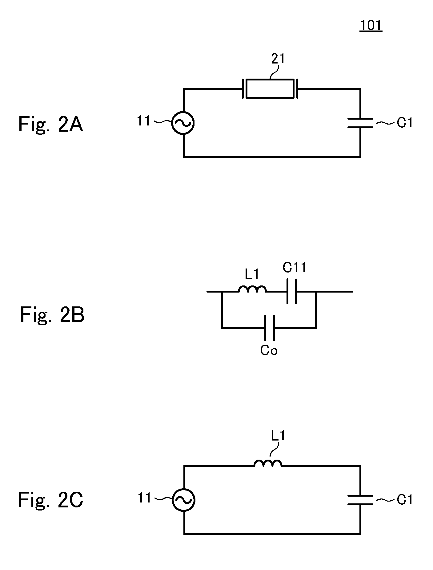
[0028]A power transmitting device according to a first embodiment will be described with reference to FIGS. 2A to 2C and FIG. 3.

[0029]FIG. 2A is a circuit diagram of a uncoupled power transmitting device 101 according to the first embodiment. The power transmitting device 101 includes a high-frequency voltage generator 11, and a piezoelectric resonator 21. The equivalent capacitor C1 represents the capacitance obtained between the two generating electrodes when no receiving device is present. The piezoelectric resonator 21 and the capacitor C1 are connected in series to the high-frequency voltage generator 11.

[0030]FIG. 2B is an equivalent circuit of the piezoelectric resonator 21. FIG. 3 is a graph illustrating the frequency characteristics of the impedance and phase of the piezoelectric resonator 21. In FIG. 3, a logarithmic scale is used for the impedance axis (vertical axis), and a linear scale is used for the frequency axis (horizontal axis). The piezoelectric resonator 21 is r...

second embodiment

[0034]FIG. 4A is a circuit diagram of an uncoupled power receiving device 201 according to a second embodiment. The power receiving device 201 includes a piezoelectric resonator 22, and a load RL. The equivalent capacitor C2 represents the capacitance obtained between the two electromotive electrodes when no power transmitting device is present. The piezoelectric resonator 22 and the load RL is connected in series to the capacitor C2.

[0035]FIG. 4B is an equivalent circuit of the piezoelectric resonator 22. As illustrated in FIG. 4B, the piezoelectric resonator 22 is represented by a parallel circuit formed of a capacitor Co and a series circuit formed of an inductor L2 and a capacitor C21. This equivalent circuit is similar to the one illustrated in FIG. 2B in the first embodiment, and has frequency characteristics similar to those illustrated in FIG. 3.

[0036]FIG. 4C is an equivalent circuit of the power receiving device 201 according to the second embodiment for the case where the ...

third embodiment

[0038]All the electrodes are interacting through a dielectric medium (including air and vacuum). The quasi static-situation (negligible far field radiation) in case of four electrodes (one generator, one load), is fully described by a 4×4 matrix involving 10 different capacitive coefficients. In case of a two port representation of the system, the power transfer is fully described in the classical circuit frame by two coupled equivalent capacitors C1 and C2 and a mutual capacitance CM or equivalently a coupling factor k. These values can be derived from the 10 independent general coefficients of the original matrix and will be referred in the following as the two-port three-coefficient coupling model.

[0039]In some practical situations the behavior is dominated by some specific coefficients among the many involved, for instance the coupling coefficients between on one hand the active electrodes and on the other hand the passive ones.

[0040]FIG. 5 is a circuit diagram of a power transm...


PUM


Abstract

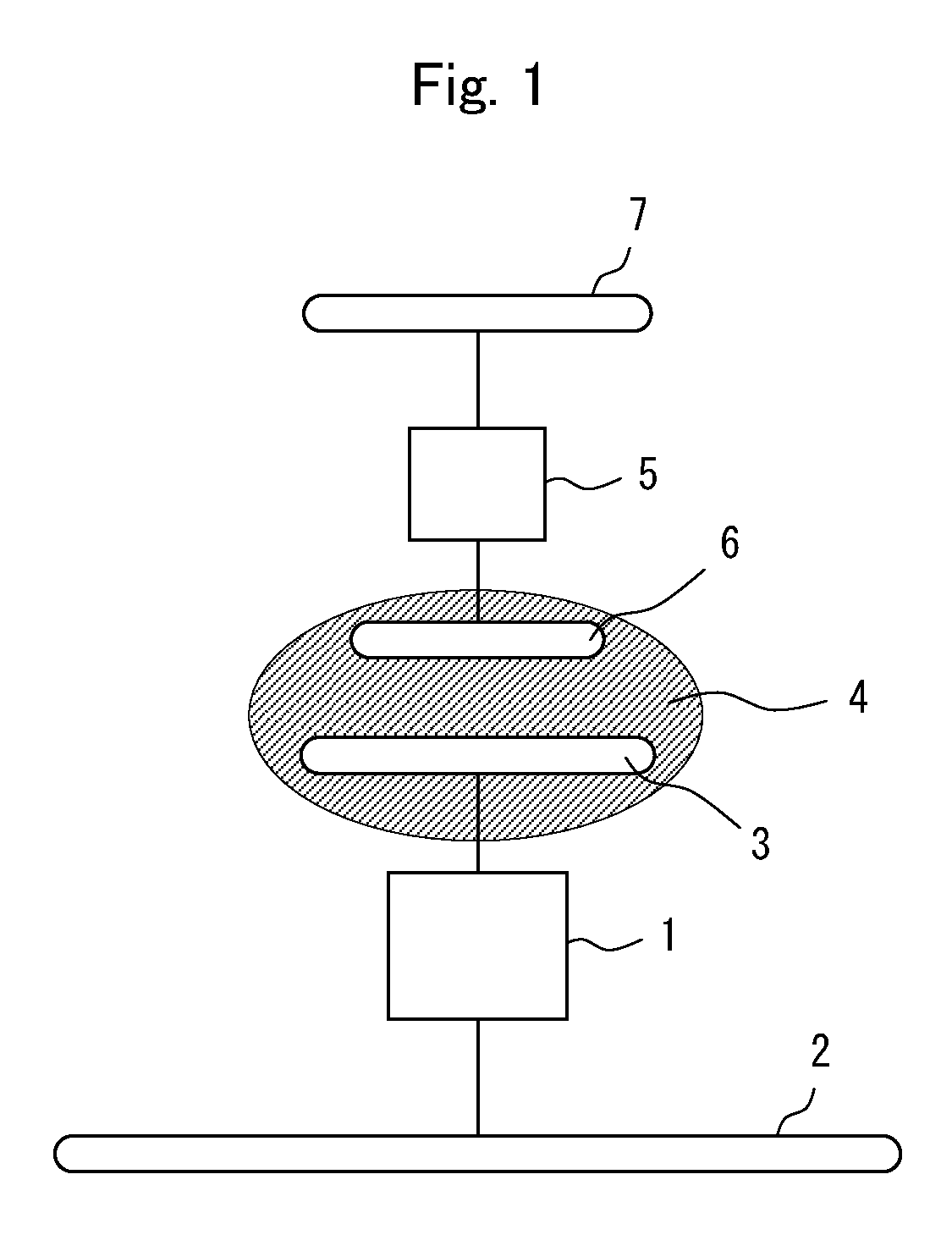
A power transmission system that includes a power transmitting device and a power receiving device. The power transmitting device includes a high-frequency voltage generator, a piezoelectric resonator, a power transmitting device side passive electrode, and a power transmitting device side active electrode. The power receiving device includes a piezoelectric resonator, a load, a power receiving device side passive electrode, and a power receiving device side active electrode. The active electrode of the power transmitting device and the active electrode of the power receiving device are in proximity with each other, whereby the power transmitting device and the power receiving device are capacitively coupled through the active electrodes and the surrounding dielectric medium.

Description

CROSS REFERENCE TO RELATED APPLICATIONS[0001]The present application is a continuation of International application No. PCT / JP2011 / 002664, filed May 13, 2011, the entire content of which is incorporated herein by reference.FIELD OF THE INVENTION[0002]The present invention relates to power transmitting devices, power receiving devices, and power transmission systems which transmit electric power in a noncontact manner.BACKGROUND OF THE INVENTION[0003]PTL 1 discloses a system configured to transmit electric power through capacitive coupling.[0004]The power transmission system described in PTL 1 includes: a power transmitting device including a high-frequency high-voltage generator, generating electrodes to define the couple of generator active / passive electrodes; a power receiving device including a high-frequency high-voltage load, and electromotive electrodes to define the load side active / passive pair.[0005]A voltage lower than that applied to the active electrode is applied to the...

Claims


Application Information

Patent Timeline
IPC IPC(8): H02J17/00
CPCH01L41/107H02J5/005H02J50/05H02J50/12H02J50/70H10N30/40H02J50/005H04B5/79
Inventor ICHIKAWA, KEIICHIBONDAR, HENRI
Owner MURATA MFG CO LTD
Learn More