Electrolytic process to produce aluminum hydroxide

a technology of electrolysis and aluminum hydroxide, which is applied in the direction of electrolysis components, energy inputs, aluminium oxides/hydroxides, etc., can solve the problems of difficult recovery of valuable aluminum and alkali metal compounds from industrial waste streams containing alkali aluminate, and achieve the effect of increasing the efficiency of the apparatus and method

Inactive Publication Date: 2012-11-22
CERAMTEC
View PDF1 Cites 24 Cited by
  • Summary
  • Abstract
  • Description
  • Claims
  • Application Information

AI Technical Summary

Benefits of technology

[0006]The disclosed methods are enabled by the use of an alkali ion conductive membrane in an electrolytic cell. The alkali ion conductive membrane may include a chemically stable ionic-selective ceramic membrane. A layered composite of a chemically stable ionic-selective polymer and a cation-conductive ceramic membrane may also be used to take advantage of the chemical stability of the ionic-selective polymer and the high alkali-ion selectivity of cation-conductive ceramic materials.
[0011]The free alkali ions (M+) are transported from the anolyte compartment to the catholyte compartment through the alkali ion conductive membrane. The removal of alkali ions from the anolyte compartment further facilitates formation of aluminum hydroxide.
[0019]To increase the efficiency of the apparatus and method, hydrogen gas produced in the catholyte compartment may be collected or used to generate power for use in the process.

Problems solved by technology

It has proven difficult to recover valuable aluminum and alkali metal compounds from industrial waste streams containing alkali aluminate.

Method used


Image

  • Electrolytic process to produce aluminum hydroxide
  • Electrolytic process to produce aluminum hydroxide
  • Electrolytic process to produce aluminum hydroxide

Examples


example 1

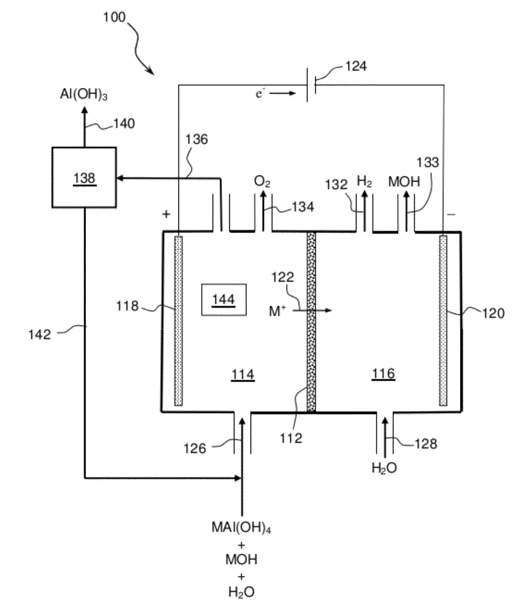
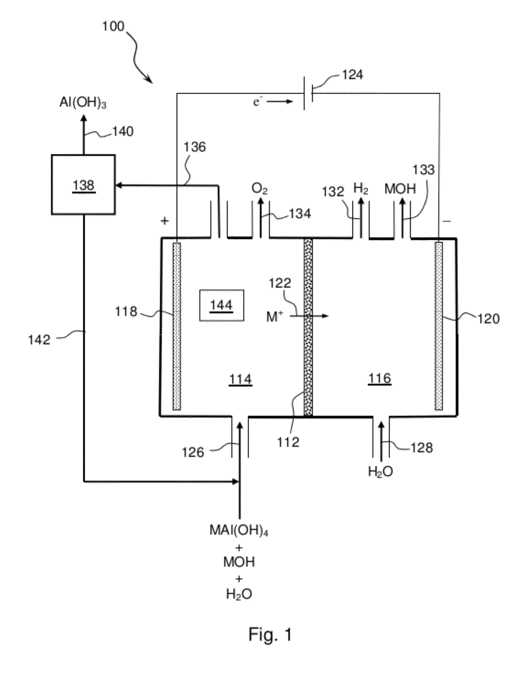
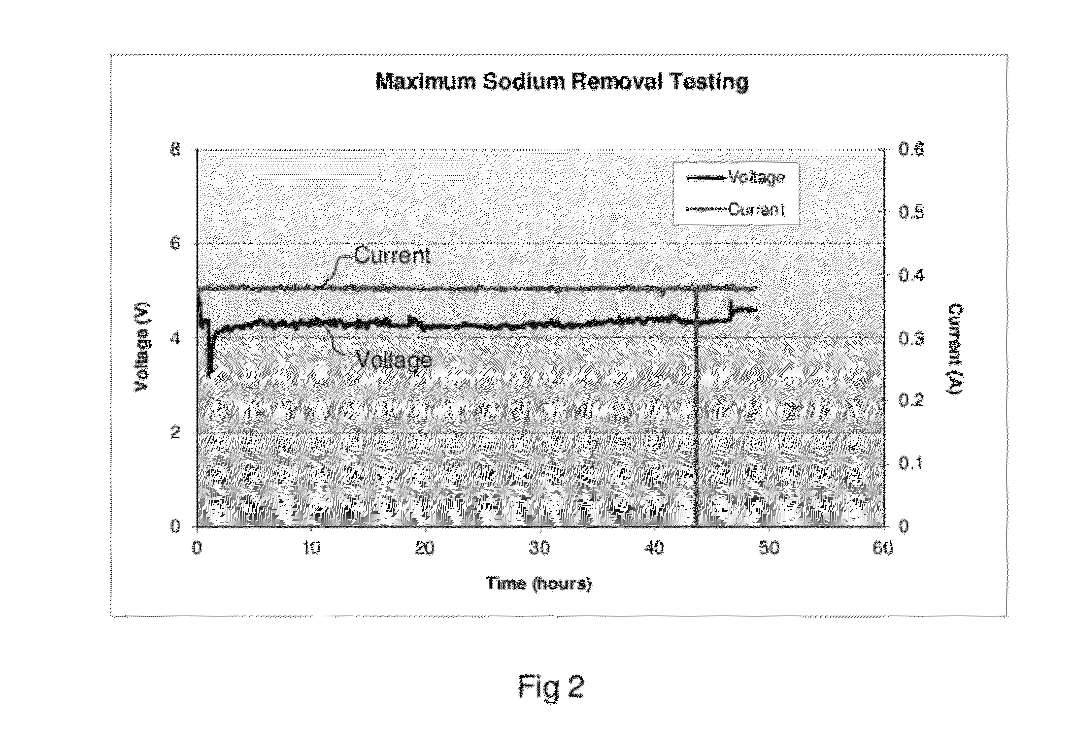
[0052]A solution containing 5.64 molarity of NaOH in solution sodium aluminate waste stream was heated to 40° C. as the anolyte. The anode was Kovar (Fe—Ni—Co) and the cathode was Kovar. The cell was operated in a batch mode of operation at a current density of 75 mA per sq.cm. of membrane area. The initial catholyte was 1M NaOH. FIG. 2 is a plot which presents the sodium transfer current-versus voltage to drive sodium across the two compartment cell to thereby separate sodium from sodium aluminate.

[0053]The voltage remained between 4 to 5 volts during the entire duration for majority of the test. It should be noted that the cell was operated for a known duration in batch mode to establish cell performance only. A total of 82.7% of sodium was separated from the sodium aluminate sample in this test as determined by ICP analysis. FIG. 3 shows samples collected at different level of sodium separation with membrane cell and formation of aluminum hydroxide. The level of sodium separation...

example 2

[0058]A NaSICON membrane was assembled in a two-compartment cell configuration and operated an in electrochemical cell with anolyte and catholyte solutions. Operated at constant current density of 75 mA / cm2, several batch tests were conducted to demonstrate the approach to produce sodium hydroxide and aluminum hydroxide from the waste sodium aluminate based sample. The electrolytic cell was operated for about 20 hours at 40° C. The initial and final anolyte and catholyte solutions were submitted for sodium mass balance analysis to determine the sodium concentration. The average power consumption to make NaOH was determined from the sodium mass balance analysis results.

[0059]FIG. 6 is a plot which presents the sodium transfer at constant current, the voltage is the potential required to drive sodium across the two compartment cell operated in batch mode as a function of time to thereby separate sodium from sodium aluminate in multiple batch testing. The voltage remained between 4 to ...


PUM

PropertyMeasurementUnit
temperatureaaaaaaaaaa
conductiveaaaaaaaaaa
electric currentaaaaaaaaaa

Abstract

Methods and apparatus for separating aqueous solution of alkali aluminate into alkali hydroxide and aluminate hydroxide are disclosed. These methods are enabled by the use of alkali ion conductive membranes in electrolytic cells that are chemically stable and alkali ion selective. The alkali ion conductive membrane includes a chemically stable ionic-selective cation membrane.

Description

CROSS-REFERENCE TO RELATED APPLICATIONS[0001]This application claims the benefit of U.S. Provisional Application No. 61 / 513,825, filed Aug. 1, 2011. This application is a continuation-in-part of U.S. patent application Ser. No. 13 / 223,045, filed Aug. 31, 2011, and entitled “Electrochemical Process to Recycle Aqueous Alkali Chemicals Using Ceramic Ion Conducting Membranes,” which is a divisional of U.S. patent application Ser. No. 12 / 062,458, filed Apr. 2, 2008, and entitled “Electrochemical Process to Recycle Aqueous Alkali Chemicals Using Ceramic Ion Conducting Membranes.” These patent applications are expressly incorporated herein by reference.BACKGROUND OF THE INVENTION[0002]Alkali aluminate compounds are obtained in various industrial reactions. For example, sodium aluminate is formed by the reaction of aluminum metal with sodium hydroxide as follows:2Al+2NaOH+6H2O→2NaAl(OH)4+3H2 [0003]Alkali aluminate is formed by the neutralization of aluminum oxide (alumina) with a base, such...

Claims


Application Information

Patent Timeline
Patent Type & Authority Applications(United States)
IPC IPC(8): C25B1/00C25B9/08C25B9/19
CPCC25B1/00C25B13/04C25B15/08C01P2004/61C01P2002/72C01P2004/03C01P2004/20C01F7/02Y02P20/129
Inventor BALAGOPAL, SHEKARDUFFEY, KEAN
Owner CERAMTEC
Why Eureka
Try Eureka